Google statistics

Friday, 14 November 2014

DIY 1x12'' Cabinet Speaker - Vintage 30 8Ω 2'' speaker

DIY 1x12'' Cabinet Speaker - Vintage 30 8Ω 12'' speaker

In order to test the TubeSim 25W 8Ω output I decided to make a DIY 1x12'' cabinet speaker with a classic Celestion Vintage30 8Ω speaker installed.
I was inspired by the series of 4 magnificent and instructive videos made by thefirstbab. The first one of the series can be seen here:

I changed the dimensions of this cabinet based on a 1912 Marshall to provide nicer proportions to the cabinet. To do so, I used (approximately) the golden ratio 0.618 and came up with the following external dimensions: 600 x 400 x 300 mm (W x H x D) for a total internal volume of approximately 50 liters.
I used 18 mm (3/4'' approx.) thick plywood (from exotic okoumé wood) already precut acquired in a DIY store. The wood cleats were cut from two 22 mm x 2400 mm beech squares
The panels are fixed with wood glue and 3.5 x 30 mm wood screws. Wood filler paste was used to fill holes and imperfections. Find here below the cabinet mechanical drawings (AutoCAD was used but open source LibreCAD can also be used)

The first step is to glue and screw the bottom panel to both sides. To ease screwing, 2 mm holes are drilled. In order to hide the head screws, shorter 6 mm holes are drilled too, once the panels have been glued and screwed together, wood filler paste is applied to completely hide holes and head screws. Then the top panel is glued and screwed to both sides.

Four 22 mm x 564 mm thick wood cleats are placed on the internal top, bottom, front and back sides. Note that front cleats are fixed aligned to the front borders, while rear cleats are fixed leaving 20 mm space to the rear borders to allow adding external rear cover panels. Picture below shows the bottom wood cleats glued.

Two 22 mm x 320 mm wood cleats are glued and screwed to the front left and right sides. Shorter and beveled wood cleats 22 x 270/242.5 are fixed on the rear left and right sides. This shape allows introducing the front panel that will hold the speaker. The picture below shows the wood cleats glued, ready to be screwed. The 2 short beveled cleats resulting from cutting must be reserved to finish the rear frame once the front panel is installed.
Two beveled cleats 22 mm x 210/189 mm are fixed on the bottom sides, while shorter beveled cleats 22 mm x 107/85 mm are fixed on the top sides. This allows sliding the front cover from the rear top of the case, place the bottom side of the front cover panel onto the internal bottom front side and then pivot the front cover panel to place the top side on the internal top front side of the case as shown by the red traces of the mechanical drawing, see the two pictures below. To allow this pivotal movement, top side reinforcement beveled cleats must be shorter.
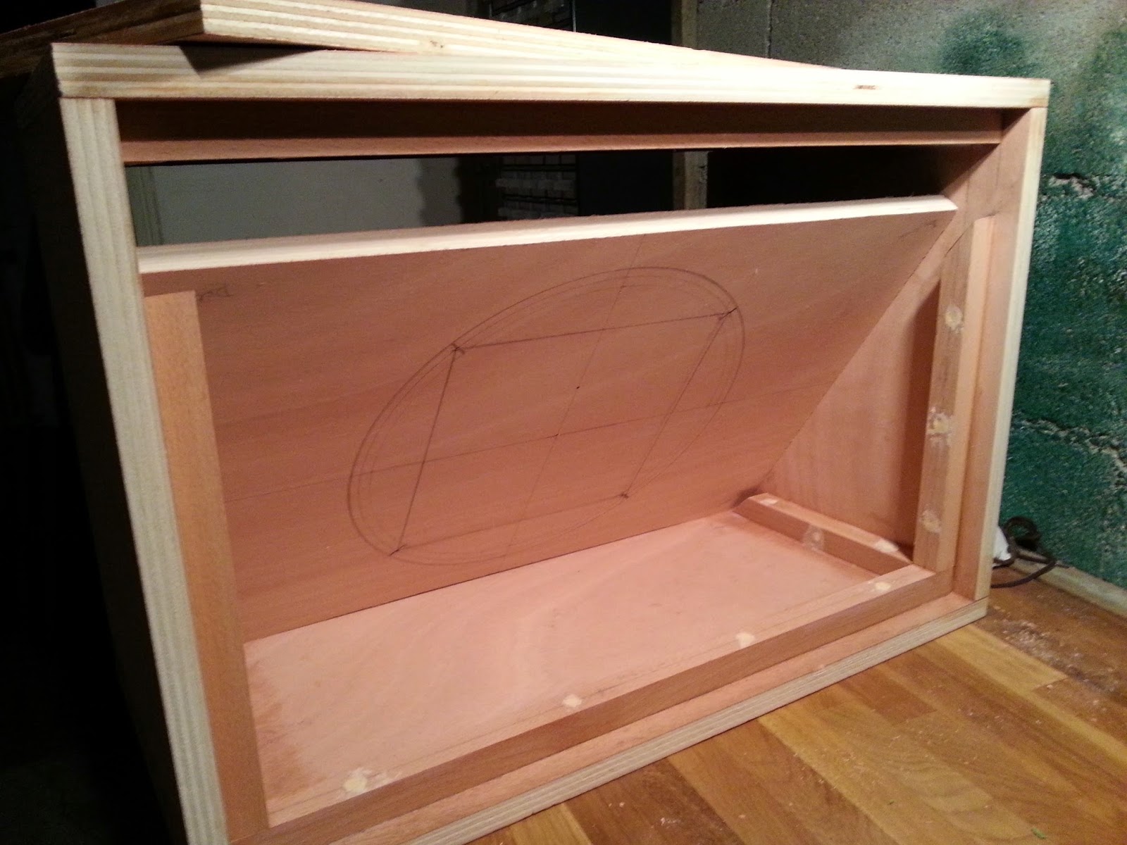
Three circles of Ø283 mm, Ø297 mm, Ø309 mm respectively are drawn in the center of the front cover as recommended by the speaker manufacturer Celestion for the Vintage 30 model. The position of the four speaker fixing screws are also drawn, they are 210 mm apart from closest screw, horizontally and vertically.
The external circle of Ø309 mm represents the maximum dimensions of the speaker.
The middle circle of Ø297 mm represents the placement of the four screws. Logically the relationship between the diameter of the circle and the sides of the square is respected: sqrt(2*210*210) = 297 mm.
The internal circle of Ø283 mm diameter represents the hole that must be left for the speaker sound to come out of the box. An electrical jigsaw has been used to make this hole and then the borders slightly softened with a wood file and sandpaper.
All external sides and corners must be rounded. I don't have a router, so I had to use a wood file. The radius of this rounding must correspond to the internal diameter of the corners used. Note that Marshall corners used in the first video have a larger non standard radius 1'' (25 mm) and rear sides are not rounded. Check this article Choosing amp corners for further info.
I purchased all cabinet and amp accessories in this great website: Tube-Town. I bought a set of 8 standard black corners 1/2'' (12.5 mm internal radius). In this case, all corners are identical and all the sides of the cabinet must be rounded, rear sides too.
I traced lines parallel to the sides at 6.3 mm and 12.5 mm (they can be seen in the first picture), with the wood file I made 45 degrees between the lines at 6.3 mm and then I finished the rounding up to the 12.5 mm lines, I cut a 12.5 mm semicircle in a thin plywood piece to be able to properly control the radius while filing, I used one of the corners to be sure that it adjusted properly to the corners of the cabinet.
I then filled in any irregularities with wood paste and sanded all the surfaces, see pictures below:


Next step is spray painting in matte black all the internal sides of the cabinet. Several layers will be needed for a good result:

Front cover is painted on both sides. Before painting it file the borders leaving at least 2 mm margin on each side and make sure that once the grill cloth is fixed on it there is enough place inside the cabinet to put the front panel in place. Speaker hole screws were previously drilled and hole borders were lowered in order to hide countersink screw heads. Head screws will have to be painted in black too, so they cannot be seen through the grill cloth. Screws will have to be put in place before fixing the grill cloth.

It's time to check the accessories fitting. I purchased a black strap with nickel ends and four rubber feet at Tube-Town.

I wanted a vintage look for the Vox AC30 TubeSim cabinet with Celestion Vintage 30, so I opted for a golden vintage grill cloth, two meters of Red basket VOX type tolex and two meters of white medium piping to enhance and frame the grill cloth.
Before fixing the grill cloth, place the front panel in place and make the holes corresponding to the fixing screws. To fix the grill cloth to the front cover I used a cheap upholstery stapler. Place the four speaker screws, before fixing the grill cloth. Use a hairdryer to heat the grill cloth before stapling it so that when cold is as stiffened as a drum batter head. It's important to select the proper staples, if they are too short or too thick they may not be pushed to the end. This actually happened to me when I fixed the white piping to the beech cleats frame, since solid beech it's a very hard material and I had to finish with some hammer taps.
Use a soldering iron to melt the grill cloth over the holes that will be used to fix the front panel with screws to the cabinet, otherwise grill cloth can be damaged when screwing the front panel to the cabinet.


Gluing tolex is probably the most tricky part of this project, at least for me, since it was the first time. I recommend watching thefirstbab video series I mentioned at the beginning of this post and also the videos from Uncle Doug:

A neoprene glue spray is recommended for gluing the tolex to the cabinet. I drew the shape of the cabinet in the back of the tolex (see picture below), marking the place where the cabinet borders had to coincide and leaving 1 cm margins. The tolex is only one piece 2m long and the joint should be placed at the center bottom of the cabinet. Corners are not yet cut, this will be made afterwards to compensate for tolerance or fabric deformation. The tolex piece is rolled inside out to ease manipulation while gluing, exposing the first 300 mm section. Glue is sprayed on the central square of the tolex section and half of the bottom cabinet side and let dry for some seconds, then applied from the center of the bottom side. With a clean cloth, press the tolex fabric from inside to outside to expel any bubbles. Glue is sprayed on one side of the cabinet and the center square of the second section, special care must be taken on the border, press the tolex on the border carefully to avoid forming bubbles. Process follows on the top side. Careful must be taken to be sure that the tolex is properly aligned to the cabinet while unrolling the tolex piece over the cabinet and the drawn lines follow the border of the cabinet.
When both tolex extremes meet on the bottom side of the cabinet, they must overlap and with the help of a ruler and a cutter they are both cut in the middle of the overlapping section, remove the top strip just cut, detach the top fabric extreme and remove the strip left on the bottom fabric, so that a perfect joint is left between the two fabric sections.
Now it is time to glue the tolex on the front and rear sides of the cabinet, this is even trickier. Follow the videos I posted before. Fold symmetrically the fabric at the corners and make a cut in the middle, overlap both sides of the fabric and make a 45 degree cut from the outer corner to the inner corner, but no longer!!, otherwise you will leave the internal borders without material, see on the drawing above how the 45 degree angles only apply to the first section of the border exposed to the front or the rear, but it does not apply to the internal sides. Any excess of glue on the tolex can be cleaned with white spirit.
Leave to dry the neoprene glue for at least 24 hours.
Cut and staple or nail down the piping to the rear side of the front frame. Put in place the front panel with the grill cloth and speaker screws and fix it with screws to the cabinet from inside.
Rubber feet and handle can be fixed now doing some small cuts on the tolex at the place corresponding to screw holes. Corners can be fixed with two screws per corner, make sure that they are properly placed with screw ears on the cabinet inside.
See below the front view of the finished speaker cabinet.
I decided to do a rear open cabinet. Given the volume of air inside the cabinet, a closed cabinet could damp the bass sound pressure waves.
From the rear panel, 2 pieces of 115 mm wide are cut for the top and bottom covers, middle cover is unused. A Ø24 mm hole is made with a wood drill at the center of the top cover to place the speaker jack. Tolex is applied to both pieces and 2 mm holes are equally spaced all around to fix both covers with screws and countersunk flange finishing washers to avoid damaging the tolex with the screws and obtain a better finishing. Radial cuts are practiced with a cutter over the tolex at the connector hole on the top cover and connector is fixed with two screws.
The speaker connector is an hybrid SpeakON/ 1/4'' jack Neutrik connector. Speaker is fixed into the front panel using washers and bolts.
speaker cable 2 x 1.5 mm2 is soldered between the speaker connector and the connector taking care of + and - connections.
Top and bottom rear panels are fixed with abundant screws and countersunk flange type washers.
See below the rear view of the finished speaker cabinet.
The 1x12'' cabinet speaker with the 25W TubeSim amplifier.
I decided to personalize the cabinet speaker adding a Rezzonics logo at the top front of the cabinet. I named the cabinet speaker Rezzonics v12 for the 1x12'' speaker installed.
I used Inkscape for the logo design, I tried several fonts: Magneto, Aeroplane Flies High, Mottel, Norton and Puma Oblique. The Magneto font is the one I most liked.
Several layers of extruded extended text are overlapped to provide a 3D volume effect, with a silver grey in the front layer, darker grey in the middle layer and black on the top layer:
I used some recycled materials to make the logo and I changed the colors: Bottom layer aluminum grey, middle layer in black and top layer in silver. A piece of 2.5 mm plywood coated with aluminium was used as the base or bottom layer. Another piece of 2 mm plywood painted in black was used for the middle layer, and a 1 mm soft plastic lined with aluminum paper for the top layer.
Printed paper was glued to the plywood pieces and then the text form sawed with a scroll saw. For the thin plastic layer I used scissors. The three layers are centered and glued and then the whole logo is lacquered.
This is the final result.
Rear view of the cabinet speaker with Celestion Vintage 30 speaker installed:
Front view of the finished cabinet with logo and 25W TubeSim amplifier.
Now it's time for the sound check and comparative with AC30 emulators!!

Thursday, 6 November 2014

Tube Simulator - Practical implementation - Test, debugging and verification (4/4)

Debugging:

For the tube amp debugging I used a digital multi-meter to verify transistors and diode polarization, as well as DC and bias voltages, a signal generator and an oscilloscope. I have a Velleman PCSGU250 Oscilloscope ($200), it has a signal generator output and a two oscilloscope channels, it connects to a PC via USB and has a simple and easy to use graphical interface, that offers frequency spectrum analysis.

Fig 1. Velleman PCSGU250 Oscilloscope ($200)
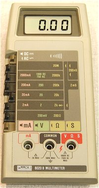
I have a vintage digital multimeter very similar to the first Fluke digital multimeter models, mine is a KT 605 (probably a Fluke copy):

I had many issues with cold soldering and oxidation due to the use of a soldering paste not suitable for electronics, this caused many DC regulators breakdowns. I had to redo many of the soldering joints.
Another issue was related to excessive noise in some of the amps stages, I had to replace some of the amps by followers to reduce the amplification of noise floor.
Film capacitors are very sensitive to high temperature and some of them had to be replaced since they where damaged while soldering. It would be better to use low temperature solder paste (Sn Bi) and hot gun to avoid heating too much capacitor pads.
25W class-D amplifier gain was set with input pins PA_GAIN[1:0]=11 to get a maximum gain of 36dB.

Verification:

Signal generator and an electric guitar were used as input of the tube amp, oscilloscope signal capture at different test points on the board are shown below.

Fig 2. shows the time signal of a G note at the output of the guitar and input of the tube amp, with approximately 0.5V peak-to-peak

Fig 2. G note (open 4th string) signal at the tube amp input
Fig 3. shows the frequency spectrum of the same signal by using the FFT function of the scope.
As it can be seen fundamental frequency of the signal is 196Hz which corresponds to a G note, open 4th string, harmonics at multiples of the fundamental frequency can be observed
Fig 3. G note frequency spectrum signal

Fig 4. shows the signal at the output of the preamp first double operational amplifier stage (TP6) (refer to schematics on the Tube Amp Schematics post), signal is amplified by almost 10, more than 4V peak-to-peak, with no apparent distortion.
Fig 4. A G note (open 4th string) at the output of preamp 1st stage (TP6)
Fig 5. shows a G note at the output of the preamp second double operational amplifier stage (TP8). Some distortion appears, with more gain on the positive cycle and some soft clipping. Signal range is around 4V peak-to-peak.
Fig 5. G note at the output of the preamp second stage (TP8)
Fig 6. shows a G note at the output of the equalizer (TP21) with bass and treble at 0. Signal range is 1.6V peak-to-peak.
Fig 6. G note at the output of equalizer (TP21). Treble = 0. Bass = 0
Fig 7. shows a G note at the output of the equalizer (TP21) with bass at 0 and treble at 10. Signal range is 1.5V peak-to-peak.
Fig 7. G note at the output of the equalizer (T21). Treble = 10, Bass = 0
Fig 8. shows a G note at the output of the equalizer (TP21) with bass at 10 and treble at 0. Signal range is 0.4V peak-to-peak.
Fig 8. G note at the output of the equalizer (T21). Treble = 0, Bass = 10
Fig 9. shows a G note at the output of the output amp first section (TP20). Distortion appears on both cycles with some hard clipping on both cycles. Signal range is around 0.8V peak-to-peak.

Fig 9. G note at the output of the output amp first section (TP20)
Fig 10. shows a G note at the output of the output amp second section (TP18). Distortion appears on both cycles with harder clipping in the negative cycles. Signal range is around 0.8V peak-to-peak.
Fig 10. G note at the output of the output amp second section (TP18)
Fig 11. shows a G note at the output of the main volume potentiometer (TP22). Signal range is around 0.6V peak-to-peak. Volume = 10
Fig 11. G note at the output of the main volume potentiometer (TP22). Volume = 10

Fig 12. shows a G note at the output of the Speaker Emulator filter first opamp (TP 25). Signal range is around 1.5V peak-to-peak. Mid frequencies are boosted.
Fig 12. G note at the output of the Speaker Emulator filter first opamp (TP25)
Fig 13. shows a G note at the output of the Speaker Emulator filter first opamp (TP 29). Signal range is around 1.5V peak-to-peak. Mid frequencies are boosted.
Fig 13. G note at the output of the Speaker Emulator filter second opamp (TP29)
Fig 14. shows a G note at the output of the Speaker Emulator filter third opamp (TP 24). Signal range is around 1.75V peak-to-peak. Mid frequencies are boosted.
Fig 14. G note at the output of the Speaker Emulator filter third opamp (TP24)
Fig 15. shows a G note at the output of the Speaker Emulator filter fourth opamp (TP 27). Signal range is around 1.6V peak-to-peak. Mid frequencies are boosted.
Fig 15. G note at the output of the Speaker Emulator filter fourth opamp (TP27)
The real signals correspond quite accurately to LTSpice simulation results.
Now is time for the sound tests, but first of all I needed a Speaker cabinet to connect to the 8ohms power amplifier output.

Monday, 20 October 2014

Tube Simulator - Practical Implementation - Chassis, face plate (3/4)

Face plate design

For the face plate design I used Inkscape. Inkscape is a free vector graphics editor and design tool for professional and amateur use. There are lots of tutorials, videos and materials for fast and easy learning. Cool free fonts can be found in the internet. It is important to install the fonts in the computer used for design but also in the computer used for printing, otherwise default fonts will be selected.
I wanted a simple design with a cool, coloured background but that could match well with the natural aluminium colour of the rest of the box, so I used a kind of steel or aluminum grey and then I used a liquid effect.
This is the result:
It's important to have the right dimensions that correspond with the placement of the potentiometers, switches, jacks and other components in the PCB layout. Since the board was mounted on standoffs in the base plate, the height of PCB and standoffs has to be considered.

The design can be very easily flipped horizontally before printing. I printed the design in A3 printing transparencies used for presentation slides with a laser printer. Since the design is printed flipped in the A3 transparent sheet, the ink stays in the side that has to be glued to the enclosure, which helps protecting the ink from scratching if it were exposed outside.

Cut out front and rear face plates from the transparent sheets and verify that everything is in the right place. You can actually see the effect of not installing the proper fonts in the computer used for printing.

Front face plate placed in position (not glued yet):
Rear face plate placed in position (not glued yet)

Chassis assembly

Before fixing the face plate to the chassis, holes must be drilled in the chassis.
Instead of using regular metal drills I recommend using a multi-drill bit and of course a drill support, a much higher precision of drilling is obtained.
Not flipped design can be printed in a regular paper, placed in position and with a hammer and a punch tool the center of the holes to be drilled can be marked.

Once the holes have been drilled, chassis cover must be put in place because very often components are not perfectly aligned or they don't have the exact diameter, so the holes must be adjusted with a file.

Once printed, the design is cut out with some scissors and fixed to the chassis faceplate using transparent glue in spray:
Aluminum chassis must be perfectly clean with no traces of dust, grease or fingerprints. Some acetone can be used for cleaning it.
The glue must dry for 2 or 3 minutes before applying to the chassis, it must be positioned carefully and properly aligned trying to avoid that bubbles form between the face plate and the chassis. Use a clean cloth and apply some force to stick the face plate to the chassis.
Once the face plate is in place, a cutter can be used to remove the face plate in those areas corresponding to the holes.


Now the chassis is fixed to the PCB and base plate, inserting the front components in their holes that were previously verified. rear components are soldered with wires to the board. Nuts are added to potentiometers, switches and jacks with black plastic spacing washers.
Insert the rubber buttons with the potentiometers completely turned anti-clockwise and the dials pointing at 0, and the job is done!!

Front view of finished chassis:
Rear view of the finished chassis

The Tube Simulator is finished, now is the time to plug it and see how it sounds!!
But wait I need a cabinet speaker to plug my Tube Simulator amplifier...

Monday, 8 September 2014

Tube Simulator - Practical Implementation - PCB layout, manufacturing, assembly (2/4)

PCB layout


The PCB has been designed in two layers, using a maximum of ground and power planes surface and numerous vias, specially in the central ground pads below ICs that dissipate more power: regulators and power audio amplifiers.

PCB width is mostly imposed by the front panel controls: switches, potentiometers and jacks.
With that in mind a proper aluminum box was chosen:
Hammond Manufacturing 1444-1372 13 x 7 x 2 inches (W x D x H) 

The L shape of the PCB leaves some space for AC power inlet, AC power switch, 1A AC fuse, AC/DC power supply, and the posibility of adding a PCB module for FX loop effects or digital reverb circuit (these modules have not been implemented yet)

Top layer


Bottom layer


PCB manufacturing


For PCB manufacturing I used Eurocircuits web site. Eagle CAD files can be uploaded and there is a very practical Price Calculator that allows having immediate quotes with options for standard pool or PCB prototypes for small PCBs . They also have the possibility to verify the PCB layout after file uploading.
I paid 140 euros (transport and taxes included) for one prototype on a 7 day working days delivery. Usually is recommended to manufacture at least two prototypes. PCBs are manufactured in Europe, they have a factory in Hungary.

Quality is very good with nice finish:

PCB assembly


The assembly drawing and the PCB ready for soldering components. SMD DC-DC converters with central pads where previously mounted using solder paste and hot soldering gun.
The solder paste that appears in the photo below was purchased in a generic DIY store and created lots of problems of oxidation. I recommend using a solder paste specific for electronic use with lowt melting temperature, usually RoHS (not leaded) solder pastes have a quite high melting point, but there are some RoHS compatible solder pastes like alloy 58 Bi / 42 Sn with a melting point as low as 138°C. The one I use is EDSYN - CR11 58/42 Bi/Sn from Farnell

It is very important to leave thermal reliefs on pads, specially in a design like this with large power and ground planes, otherwise solder iron heat will dissipate through the plane and soldering those pads will be a nightmare. I know because it happened to me.

The PCB with most of the components soldered. Rear connectors must be soldered with wires to allow PCB assembly in the chassis.

The AC/DC power supply module used was a Murata MVAD040-24 40W (23 euros) open switching power supply module with 120/230V AC@50/60Hz input and +24V DC@1.67A 40W. 


PCB mounted on the chassis aluminium base plate, with AC/DC power supply, 1A AC fuse and AC power switch:

Friday, 18 July 2014

Tube Simulator - Practical implementation - Schematics, BoM (1/4)

For the practical implementation of the Tube Simulator, Eagle CAD was used for schematics capture and PCB layout.

Component Selection and Bill of Materials:

SMD devices where used for smaller sizer, 0603 resistors are a good compromise between easy hand solderability and small size.

Texas Instruments LME49723 audio dual operational amplifier was chosen as a good compromise between low distortion, quality, cost, size, nice SOIC packaging and high power supply voltage.
I particularly like TI website for its quick and easy selection of components by means of a parameters table and a large choice of components.

Even though I am a big fan of MLCC (multilayer ceramic capacitors) I read in a series of articles in EDN website (Signal distortion from high-K ceramic capacitors and the follow-up More about understanding the distortion mechanism of high-K MLCCs) that film capacitors are better suited for audio applications since they are more linear in its frequency response and have less harmonic distortion than ceramic capacitors. MLCC capacitors experience large changes in capacitance as the voltage across them changes, which can result in harmonic distortion. So I decided to use film capacitors everywhere where the capacitor value was key to filtering the audio signal.

But I still used MLCC for signal bypassing and power supply decoupling.

The BoM was created in the Mouser website, with a huge selection of components and hardware

This is the link to he whole Bill of Materials on the Mouser website:

Input Preamp and Output Amp Schematics (page 1)


Each opamp stage is based in the aforementioned LME49723 device consisting of two opamps.

In the first opamp stage, zener diodes are used to clip signal levels. A 6.2V zener diode BZX84C6V2LT1G is used in the positive cycles and a 4.3V zener diode BZX84C4V3LT1G is used in the negative cycles.

After the first opamp stage a Schottky diode BAT54 in series with a 470k resistor is used for soft clipping, this provides a clipping closer to germanium diodes.

On the second opamp stage there is a feedback branch with a NPN transistor (MMBT2907ALT1SMD) which has its base biased at 1.65V, a TI LM4041CIDBZ shunt voltage reference was used. Another feedback branch uses a 2.7V zener diode BZX84C2V7LT1G in series with a diode MMBD4148 and a 470ohm resistor for clipping negative cycles. A third branch used another 2.7V in series with a higher 10K resistor for soft clipping of positive cycles.

The third opamp stage is just a follower to send the signal to an external effect circuit and to the output amp section. The return is also input to this stage.

An equivalent circuit to the VOX AC30 bass/treble equalizer is placed at the input of the output amp section. The equalization switch adds a deeper mid notch when activated.

The first opamp stage of the output amp adds harder clipping with two silicon diodes MMBD4148 in parallel for clipping both positive and negative cycles. And also a schottky diode in series with a 47 ohm resistor that provides a kind of germanum diode clipping in the negative cycles.

The second opamp stage adds additional clipping in both cycles by using silicon diodes MMBD4148.

A log 100K potentiometer provides volume level control of the output amp.
The forth opamp is a double follower that sends the signal to the speaker simulator and the Line out connector.

Speaker Emulator and Headphone Amplifier Schematics (page 2)

The second page of schematics shows the speaker emulator circuit based on four Sallen-Key low-pass filter sections to provide a frequency response similar to that of a 12'' speaker like Celestion Vintage 30, as shown in a previous post. This filter enhances considerably frequencies around 2.5 kHz.

A log 100K potentiometer provides speaker emulator volume level.

A switch selects Line out signal from the speaker emulator output or the output amp to be connected to an external guitar amplifier.

The headphone input is always selected from the speaker emulator output.

The headphone amplifier used is a TI TPA6111A2D 150 mW stereo headphone amplifier in a SOIC-8 device connected to a 3.5 mm mini-jack.

25W Class D Amplifier, mounting holes, fiducials (page 3)

The third page of the schematics shows the 8ohm speaker amplifier based on a very efficient (94%) 25W Class-D amplifier TI TPA3112D1PWP with less than 0.1% THD+N from a +24V supply.

The high efficiency of this new class-D amplifiers allows a relatively high power output of 25W without the need of a heatsink on a small HTSSOP 28-pin device which considerably reduces PCB layout size. Special careful must be taken with the design of the central pad connected to the ground plane by numerous vias to allow proper heat dissipation.

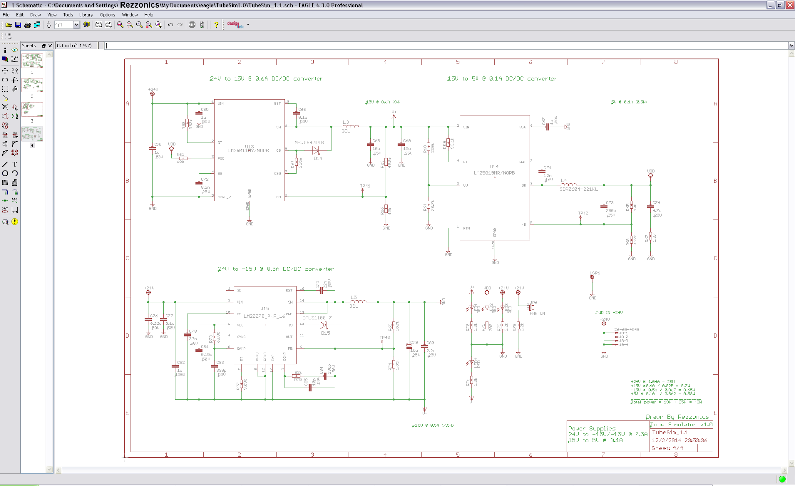
Power Supplies (page 4):

An independent switching power supply module converts 220V AC@50Hz into +24V DC. A Murata MVAD040-24 40W (23 euros) open switching power supply module is used. The module has its own PCB and is mounted inside the box with standoffs and screws.

The main PCB is then powered at 24VDC. This is the highest voltage used for output class-D 25W power amplifier.
From 24V, discrete switching regulators generate +15V and +15V  to power the operational amplifiers.
From +15V a discrete switching regulator generates +5V to power the headphone amplifier.

The maximun power consumption budget is distributed as follows:
+24V @ 1.1A = 25W for the class D speaker power amplifier (94% efficiency)
+24V to +15V @ 0.6A = 9W for the positive rail of opamps
+15V to +5V @ 0.1A  = 0.5W for the headphone amplifier
24V to -15V @ 0.5A = 7.5W for the negative rail of opamps

Total maximum power consumption is 40W

All discrete DC-DC converters have been designed using TI Webench Design Center, a very useful tool for designing power supplies that allows optimizing BoM cost, footprint and efficiency.

The Webench tool generates the whole BoM and it even allows to export schematics and layout to several of the most common CAD applications including Eagle. Sometimes the results are not very good but at least the footprint of mos common components can be created.

Most regulators are based on step-down or buck topology using integrated controllers (power switching MOSFET integrated in the controller device) except for the +24V to -15V that uses inverting buck-boost topology.

The +24 to +15V DC-DC converter is based on TI LM25011 step-down regulator.
The +24V to -15V DC-DC converter is based on TI LM25575 step-down regulator in inverting buck topology
The +15V to +5V DC-DC converter is based on TI LM25019 step-down regulator

This schematic page also includes external Power-on LED and internal SMD power-on LEDs for every power rail: +24V, +15V, -15V and +5V as well as 24VDC power in connector to main PCB from external AC-DC power supply