DIY 1x12'' Cabinet Speaker - Vintage 30 8Ω 12'' speaker
In order to test the TubeSim 25W 8Ω output I decided to make a DIY 1x12'' cabinet speaker with a classic Celestion Vintage30 8Ω speaker installed.
I was inspired by the series of 4 magnificent and instructive videos made by thefirstbab. The first one of the series can be seen here:
I changed the dimensions of this cabinet based on a 1912 Marshall to provide nicer proportions to the cabinet. To do so, I used (approximately) the golden ratio 0.618 and came up with the following external dimensions: 600 x 400 x 300 mm (W x H x D) for a total internal volume of approximately 50 liters.
I used 18 mm (3/4'' approx.) thick plywood (from exotic okoumé wood) already precut acquired in a DIY store. The wood cleats were cut from two 22 mm x 2400 mm beech squares
The panels are fixed with wood glue and 3.5 x 30 mm wood screws. Wood filler paste was used to fill holes and imperfections. Find here below the cabinet mechanical drawings (AutoCAD was used but open source LibreCAD can also be used)
The first step is to glue and screw the bottom panel to both sides. To ease screwing, 2 mm holes are drilled. In order to hide the head screws, shorter 6 mm holes are drilled too, once the panels have been glued and screwed together, wood filler paste is applied to completely hide holes and head screws. Then the top panel is glued and screwed to both sides.
Four 22 mm x 564 mm thick wood cleats are placed on the internal top, bottom, front and back sides. Note that front cleats are fixed aligned to the front borders, while rear cleats are fixed leaving 20 mm space to the rear borders to allow adding external rear cover panels. Picture below shows the bottom wood cleats glued.


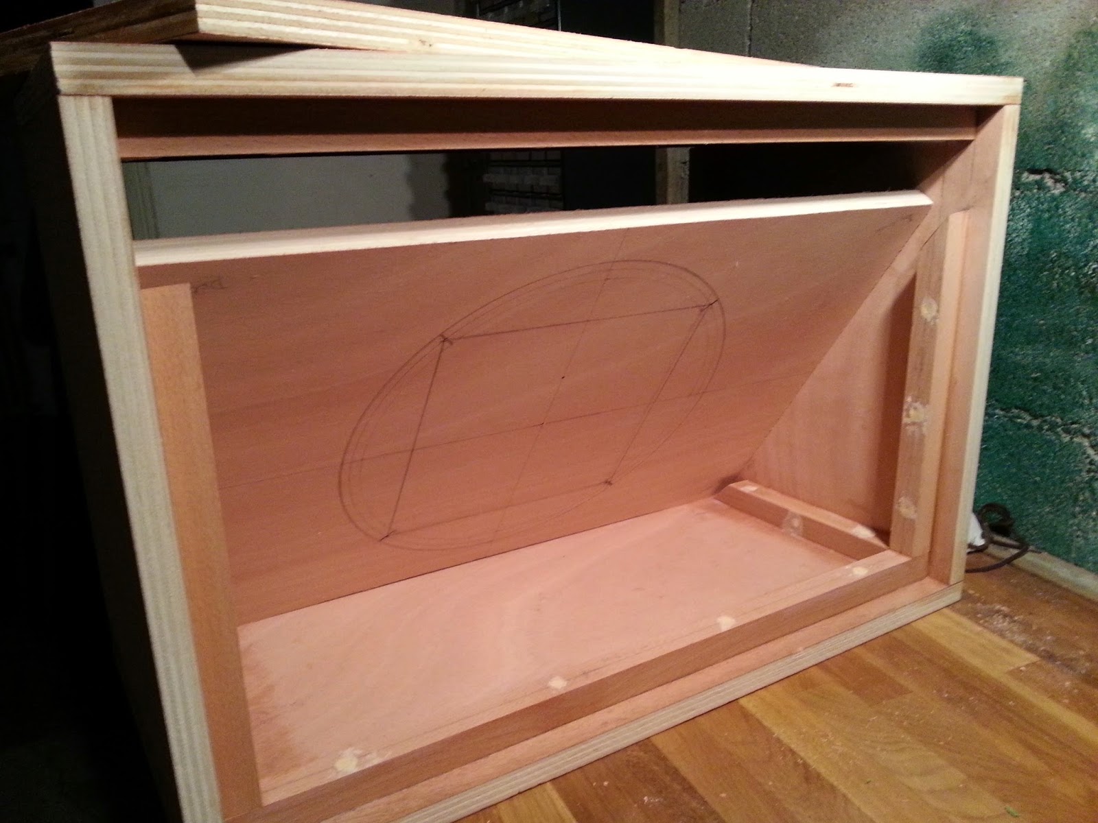
The external circle of Ø309 mm represents the maximum dimensions of the speaker.
The middle circle of Ø297 mm represents the placement of the four screws. Logically the relationship between the diameter of the circle and the sides of the square is respected: sqrt(2*210*210) = 297 mm.
The internal circle of Ø283 mm diameter represents the hole that must be left for the speaker sound to come out of the box. An electrical jigsaw has been used to make this hole and then the borders slightly softened with a wood file and sandpaper.

I purchased all cabinet and amp accessories in this great website: Tube-Town. I bought a set of 8 standard black corners 1/2'' (12.5 mm internal radius). In this case, all corners are identical and all the sides of the cabinet must be rounded, rear sides too.
I traced lines parallel to the sides at 6.3 mm and 12.5 mm (they can be seen in the first picture), with the wood file I made 45 degrees between the lines at 6.3 mm and then I finished the rounding up to the 12.5 mm lines, I cut a 12.5 mm semicircle in a thin plywood piece to be able to properly control the radius while filing, I used one of the corners to be sure that it adjusted properly to the corners of the cabinet.
I then filled in any irregularities with wood paste and sanded all the surfaces, see pictures below:


Before fixing the grill cloth, place the front panel in place and make the holes corresponding to the fixing screws. To fix the grill cloth to the front cover I used a cheap upholstery stapler. Place the four speaker screws, before fixing the grill cloth. Use a hairdryer to heat the grill cloth before stapling it so that when cold is as stiffened as a drum batter head. It's important to select the proper staples, if they are too short or too thick they may not be pushed to the end. This actually happened to me when I fixed the white piping to the beech cleats frame, since solid beech it's a very hard material and I had to finish with some hammer taps.
Use a soldering iron to melt the grill cloth over the holes that will be used to fix the front panel with screws to the cabinet, otherwise grill cloth can be damaged when screwing the front panel to the cabinet.


A neoprene glue spray is recommended for gluing the tolex to the cabinet. I drew the shape of the cabinet in the back of the tolex (see picture below), marking the place where the cabinet borders had to coincide and leaving 1 cm margins. The tolex is only one piece 2m long and the joint should be placed at the center bottom of the cabinet. Corners are not yet cut, this will be made afterwards to compensate for tolerance or fabric deformation. The tolex piece is rolled inside out to ease manipulation while gluing, exposing the first 300 mm section. Glue is sprayed on the central square of the tolex section and half of the bottom cabinet side and let dry for some seconds, then applied from the center of the bottom side. With a clean cloth, press the tolex fabric from inside to outside to expel any bubbles. Glue is sprayed on one side of the cabinet and the center square of the second section, special care must be taken on the border, press the tolex on the border carefully to avoid forming bubbles. Process follows on the top side. Careful must be taken to be sure that the tolex is properly aligned to the cabinet while unrolling the tolex piece over the cabinet and the drawn lines follow the border of the cabinet.
When both tolex extremes meet on the bottom side of the cabinet, they must overlap and with the help of a ruler and a cutter they are both cut in the middle of the overlapping section, remove the top strip just cut, detach the top fabric extreme and remove the strip left on the bottom fabric, so that a perfect joint is left between the two fabric sections.

Leave to dry the neoprene glue for at least 24 hours.
Cut and staple or nail down the piping to the rear side of the front frame. Put in place the front panel with the grill cloth and speaker screws and fix it with screws to the cabinet from inside.
Rubber feet and handle can be fixed now doing some small cuts on the tolex at the place corresponding to screw holes. Corners can be fixed with two screws per corner, make sure that they are properly placed with screw ears on the cabinet inside.
See below the front view of the finished speaker cabinet.

From the rear panel, 2 pieces of 115 mm wide are cut for the top and bottom covers, middle cover is unused. A Ø24 mm hole is made with a wood drill at the center of the top cover to place the speaker jack. Tolex is applied to both pieces and 2 mm holes are equally spaced all around to fix both covers with screws and countersunk flange finishing washers to avoid damaging the tolex with the screws and obtain a better finishing. Radial cuts are practiced with a cutter over the tolex at the connector hole on the top cover and connector is fixed with two screws.
The speaker connector is an hybrid SpeakON/ 1/4'' jack Neutrik connector. Speaker is fixed into the front panel using washers and bolts.
A speaker cable 2 x 1.5 mm2 is soldered between the speaker connector and the connector taking care of + and - connections.
Top and bottom rear panels are fixed with abundant screws and countersunk flange type washers.
See below the rear view of the finished speaker cabinet.


I used Inkscape for the logo design, I tried several fonts: Magneto, Aeroplane Flies High, Mottel, Norton and Puma Oblique. The Magneto font is the one I most liked.
Several layers of extruded extended text are overlapped to provide a 3D volume effect, with a silver grey in the front layer, darker grey in the middle layer and black on the top layer:

Printed paper was glued to the plywood pieces and then the text form sawed with a scroll saw. For the thin plastic layer I used scissors. The three layers are centered and glued and then the whole logo is lacquered.
This is the final result.


In order to test the TubeSim 25W 8Ω output I decided to make a DIY 1x12'' cabinet speaker with a classic Celestion Vintage30 8Ω speaker ... sspeakerbox.blogspot.com
ReplyDeleteU Z MAN !!!
ReplyDeleteThanx for sharing friend!! Will use your project!
I don't know how got to your page but I am glad I did! I have browsed the whole thing and to me this blog is gem. Now I really want to finish my own projects.
ReplyDeleteLooking forward to your final thought on the NuTube.
Wow! Great build and awesome details!
ReplyDeleteSome people at my church are making me a cabinet. They want to do it closed back though and then put it all into an isolation contraption (they're thinking an attachable front panel with mic routing). Would closing the back and then putting an airtight front on it change the dimensions we need to use at all? Their goal is to make it in a way that (almost) no sound leaks out. Thanks!
I know it says "unknown" but I'll get an email with your replies. Thank you!
Neil
To be honest with you I decided to use an open back cabinet in order not to deal with design complexities, I actually made a removable back panel, but the open back was good enough for me. A speaker in a closed cabinet has more difficulty in moving the air, but if width, depth and height are different, you have different resonant frequencies, which is much better than having a cubical cabinet,and that's where the golden ratio comes into place.
ReplyDeleteHola, me estoy haciendo una cabina, pantalla, gabinete, bafle, con medidas iguales y con madera enchapada de pino radiata o insigne...a pesar de tener 9 años la publicación, sigue siendo muy util e instructiva. Muchas gracias.
ReplyDelete