Korg NuTube 6P1 sounds are published here:
12AX7 starved tube sounds are published here:
Google statistics
Sunday 17 September 2017
Wednesday 9 August 2017
Korg Nutube 6P1 vs 12AX7 tube: Hybrid Amplifier (6)
Distortion analysis
A 1kHz 600mVpp sinewave is injected into the amp input, the waveform and spectrum at the output is analyzed for several gain values (0, 0.5, 1) to check the level of 2nd and 3rd order harmonics.The volume level at 1kHz is set at 0dB for the maximum gain values (G1 = G2 = 1) and the relative attenuation is shown for different gain values combinations. The level in dB at 1kHz, 2kHz and 3KHz is measured. The relative attenuation of the second and third harmonic respect to 1kHz is also measured.
NuTube 6P1 results
With BOOST off:G1 generates an attenuation of 1 and 4dB at G1= 0.5 and 0 respectively
G2 generates an attenuation of 4 and 19dB at G2= 0.5 and 0 respectively
Second harmonic has an attenuation of 20 dB (G2=1), 20 dB (at G2=0.5) and 21 dB (at G2=0)
Third harmonic has an attenuation of 35dB (G2=1), 36 dB (at G2=0.5) and 39 dB (at G2=0)
As we can see there is almost the same harmonic distortion at all gain levels.
With BOOST on:
G1 generates an attenuation of 0 and 1dB at G1= 0.5 and 0 respectively
G2 generates an attenuation of 4 and 19dB at G2= 0.5 and 0 respectively
Second harmonic has an attenuation of 10 dB (G2=1), 12 dB (at G2=0.5) and 16 dB (at G2=0)
Third harmonic has an attenuation of 21 dB (G2=1), 21 dB (at G2=0.5) and 23 dB (at G2=0)
As we can see there is a bit more harmonic distortion at higher gain levels.
Harmonic distortion is higher with BOOST on, this means that some distortion happens in the last JFET amplifier stage and some at the triode amplifier stages.
| G1 | G2 | Boost | Vpp (mV) | Att (dB) | 1kHz (dB) | 2kHz (dB | 3kHz (dB) | 2nd /1st (dB) | 3rd/1st (dB) |
| 0.0 | 0.0 | 0 | 31 | -23 | -24 | -44 | -63 | -20 | -39 |
| 0.0 | 0.5 | 0 | 162 | -8 | -9 | -29 | -48 | -21 | -39 |
| 0.0 | 1.0 | 0 | 275 | -4 | -4 | -25 | -43 | -21 | -39 |
| 0.5 | 0.0 | 0 | 40 | -20 | -21 | -41 | -58 | -20 | -36 |
| 0.5 | 0.5 | 0 | 211 | -6 | -6 | -26 | -43 | -20 | -37 |
| 0.5 | 1.0 | 0 | 358 | -1 | -2 | -22 | -38 | -20 | -36 |
| 1.0 | 0.0 | 0 | 46 | -19 | -20 | -40 | -55 | -20 | -35 |
| 1.0 | 0.5 | 0 | 249 | -4 | -5 | -24 | -40 | -19 | -35 |
| 1.0 | 1.0 | 0 | 415 | 0 | 0 | -20 | -35 | -20 | -35 |
| 0.0 | 0.0 | 1 | 306 | -20 | -20 | -37 | -44 | -16 | -24 |
| 0.0 | 0.5 | 1 | 1747 | -5 | -5 | -21 | -29 | -16 | -23 |
| 0.0 | 1.0 | 1 | 2800 | -1 | -1 | -17 | -23 | -16 | -22 |
| 0.5 | 0.0 | 1 | 334 | -19 | -20 | -32 | -41 | -12 | -21 |
| 0.5 | 0.5 | 1 | 1937 | -4 | -5 | -17 | -26 | -12 | -21 |
| 0.5 | 1.0 | 1 | 3000 | 0 | -1 | -13 | -21 | -12 | -21 |
| 1.0 | 0.0 | 1 | 350 | -19 | -20 | -30 | -41 | -11 | -21 |
| 1.0 | 0.5 | 1 | 1958 | -4 | -4 | -15 | -25 | -10 | -21 |
| 1.0 | 1.0 | 1 | 3080 | 0 | 0 | -11 | -21 | -11 | -21 |
12AX7 results
With BOOST off:G1 generates an attenuation of 1 and 5dB at G1= 0.5 and 0 respectively
G2 generates an attenuation of 4 and 17dB at G2= 0.5 and 0 respectively
Second harmonic has an attenuation of 3 dB (G2=1), 8 dB (at G2=0.5) and 17 dB (at G2=0)
Third harmonic has an attenuation of 8 dB (G2=1), 12 dB (at G2=0.5) and 21 dB (at G2=0)
As we can see there is more harmonic distortion at higher gain levels, as expected.
With BOOST on:
G1 generates an attenuation of 0 and 3dB at G1= 0.5 and 0 respectively
G2 generates an attenuation of 4 and 18dB at G2= 0.5 and 0 respectively
Second harmonic has an attenuation of 4 dB (G2=1), 8 dB (at G2=0.5) and 19 dB (at G2=0)
Third harmonic has an attenuation of 11 dB (G2=1), 15 dB (at G2=0.5) and 21 dB (at G2=0)
As we can see there is more harmonic distortion at higher gain levels, which means that distortion and saturation depends a lot on tube grid input level.
Harmonic distortion is similar with BOOST off or on, since the BOOST happens in the last JFET amplifier stage this means that most of the distortion happens in the tube amplifier stages.
| G1 | G2 | Boost | Vpp (mV) | Att (dB) | 1kHz (dB) | 2kHz (dB | 3kHz (dB) | 2nd /1st (dB) | 3rd/1st (dB) |
| 0.0 | 0.0 | 0 | 55 | -26 | -22 | -39 | -43 | -17 | -21 |
| 0.0 | 0.5 | 0 | 265 | -12 | -8 | -26 | -29 | -17 | -21 |
| 0.0 | 1.0 | 0 | 380 | -9 | -5 | -22 | -25 | -17 | -20 |
| 0.5 | 0.0 | 0 | 103 | -20 | -19 | -26 | -30 | -8 | -12 |
| 0.5 | 0.5 | 0 | 480 | -7 | -5 | -13 | -16 | -8 | -12 |
| 0.5 | 1.0 | 0 | 732 | -3 | -1 | -9 | -12 | -8 | -11 |
| 1.0 | 0.0 | 0 | 147 | -17 | -18 | -21 | -26 | -3 | -8 |
| 1.0 | 0.5 | 0 | 670 | -4 | -4 | -7 | -13 | -3 | -8 |
| 1.0 | 1.0 | 0 | 1060 | 0 | 0 | -3 | -8 | -3 | -8 |
| 0.0 | 0.0 | 1 | 248 | -24 | -21 | -40 | -42 | -19 | -21 |
| 0.0 | 0.5 | 1 | 1300 | -10 | -7 | -26 | -28 | -19 | -21 |
| 0.0 | 1.0 | 1 | 2025 | -6 | -3 | -19 | -22 | -16 | -19 |
| 0.5 | 0.0 | 1 | 442 | -19 | -18 | -26 | -32 | -8 | -15 |
| 0.5 | 0.5 | 1 | 2272 | -5 | -3 | -12 | -18 | -8 | -15 |
| 0.5 | 1.0 | 1 | 3280 | -2 | 0 | -9 | -12 | -9 | -12 |
| 1.0 | 0.0 | 1 | 530 | -18 | -18 | -21 | -31 | -4 | -13 |
| 1.0 | 0.5 | 1 | 2705 | -4 | -4 | -7 | -17 | -4 | -13 |
| 1.0 | 1.0 | 1 | 4060 | 0 | 0 | -4 | -11 | -4 | -11 |
Conclusion
More harmonic distortion is observed in the 12AX7 tube than in the NuTube.
It is easier to obtain grid clipping and saturation in the 12AX7 tube than in the NuTube.
Sunday 30 July 2017
Korg Nutube 6P1 vs 12AX7 tube: Hybrid Amplifier (5)
12AX7/12AU7 Hybrid Amplifier circuit test and verification
Below a close picture of the 12AX7 tube powered on.
| 12AX7/12AU7 |
A picture of the whole board powered on.
Left orange LED is +24V power on, right orange LED is +5V power on.Top sliding switch is +24V on/off, just below is the +5V on/off switch. To the right is the Gain Boost on/off for the power amp 8ohm speaker section, just below, the blue potentiometer, is the output gain control, below is the Gain Boost switch for the headphones/line-out section, below it is the power amp volume, below at the bottom is the headphones/line-out volume.
On the left at the bottom are the three controls for the 3-band equalizer, based on a Fender tone stack: bass, mid and treble. Above the bass control is the input gain (it has no real effect on the 12AX7/12AU7 amplifier.
The 24-pins TSSOP device on the right is the 25W class-D power amplifier.
12AX7 tube is plugged into a socket.
| 12AU7/12AX7 Hybrid 25W Amplifier |
Wave signal verification with oscilloscope
Summary of results:
- First JFET amplifier gain is 0 dB
- First 12AX7 tube stage gain is 10dB
- Second JFET buffer gain is 0 dB
- 3-band equalizer gain at 1kHz with Bass, Mid and Top = 0.5 is -17dB
- Second 12AX7 tube stage gain is 8.5 dB
- Third JFET amplifier gain with gain control and Boost Off:
- G2=0.0 =>-22 dB
- G2=0.5 => -8 dB
- G2=1.0 => -5 dB
- Third JFET amplifier gain with gain control and Boost ON:
- G2=0.0 => 3 dB
- G2=0.5 => 17 dB
- G2=1.0 => 20 dB
Maximum output level is 7880mVpp which corresponds to a maximum total gain of 22.4dB
 |
| Input signal: Sine wave 600mVpp 1kHz |
 |
| TP2 signal after first JFET buffer 600 mVpp (0 dB) |
 |
| TP4 signal after first triode anode 1900mVpp (10 dB) |
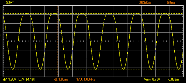 |
| C16 signal after second JFET buffer 1900mVpp (0 dB) |
 |
| C20 signal after 3-band equalizer 280mVpp. Treble=Middle=Bass = 0.5 (-17 dB) |
 |
| TP21 signal after third JFET buffer 290mVpp (0 dB) |
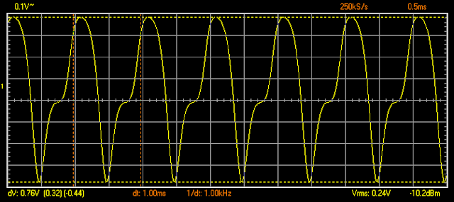 |
| TP5 signal after second triode anode 760mVpp (8.5 dB) |
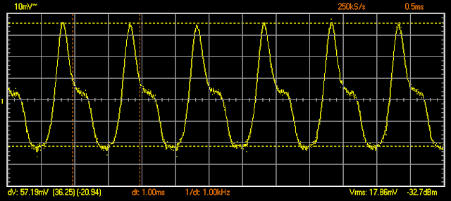 |
| C27 signal after fourth JFET amplifier 57mV, Gain 2 = 0 (-22.5 dB) |
 |
| C27 signal after fourth JFET amplifier 300mV, Gain 2 = 0.5 (-8 dB) |
 |
| C27 signal after fourth JFET amplifier 450mV, Gain 2 = 1.0 (-4.6 dB) |
 |
| C27 signal after fourth JFET amplifier 1100mV, Gain 2 = 0.0. BOOST ON (3.2 dB) |
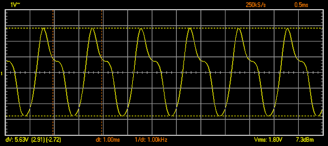 |
| C27 signal after fourth JFET amplifier 5630mV, Gain 2 = 0.5. BOOST ON (17.4 dB) |
 |
| C27 signal after fourth JFET amplifier 7880mV, Gain 2 = 1.0. BOOST ON (20.3 dB) |
Korg Nutube 6P1 vs 12AX7 tube: Hybrid Amplifier (4)
Korg Nutube 6P1 Hybrid Amplifier circuit test and verification
Below a close picture of the Korg NuTube 6P1 powered on.
 |
| Korg Nutube 6P1 |
Blue LED is +24V power on, greeen LED is +5V power on.Top sliding switch is +24V on/off, just below is the +5V on/off switch. To the right is the Gain Boost on/off for the power amp 8ohm speaker section, just below, the blue potentiometer, is the output gain control, below is the Gain Boost switch for the headphones/line-out section, below it is the power amp volume, below at the bottom is the headphones/line-out volume.
On the left at the bottom are the three controls for the 3-band equalizer, based on a Fender tone stack: bass, mid and trebles. Above the bass control is the input gain.
The 24-pins TSSOP device on the right is the 25W class-D power amplifier.
NuTube 6P1 is plugged into a 2mm pitch socket resting over 2 rubber bumpers to avoid vibrations that could pick microphonic noise.
 |
| Korg Nutube 6P1 Hybrid 25W Amplifier |
Wave signal verification with oscilloscope
Summary of results:- First JFET amplifier gain with gain control
- G1=0.0 =>-2.7 dB
- G1=0.5 => 0.1 dB
- G1=1.0 => 1.6 dB
- First NuTube 6P1 triode stage gain is 14dB
- Second JFET buffer gain is 0dB
- 3-band equalizer gain at 1kHz with Bass, Mid and Top = 0.5 is -18dB
- Second NuTube 6P1 triode stage gain is 15dB
- Third JFET amplifier gain with gain control and Boost Off:
- G2=0.0 =>-20 dB
- G2=0.5 => -5 dB
- G2=1.0 => -1 dB
- Third JFET amplifier gain with gain control and Boost ON:
- G2=0.0 =>-2.5 dB
- G2=0.5 => 12 dB
- G2=1.0 => 15 dB
 |
| Input signal: Sine wave 600mVpp 1kHz |
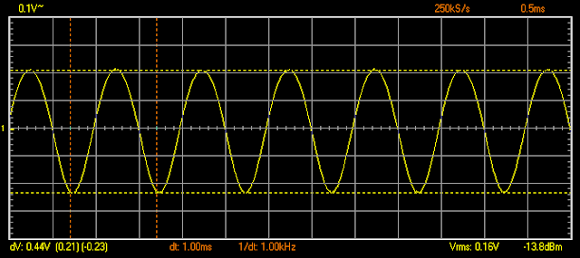 |
| TP2 signal after first JFET buffer 440 mVpp. Gain 1 = 0.0 (-2.7 dB) |
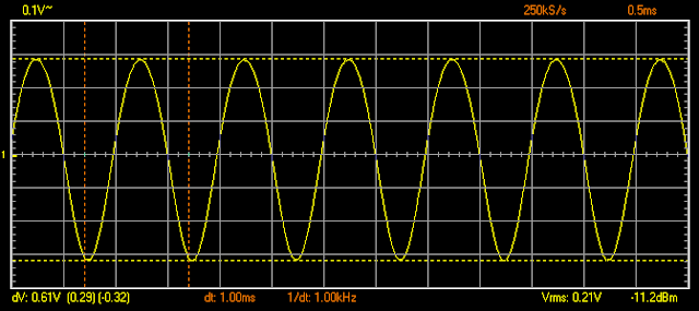 |
| TP2 signal after first JFET buffer 610 mVpp. Gain 1 = 0.5. (0.1 dB) |
 |
| TP2 signal after first JFET buffer 720 mVpp. Gain 1 = 1.0 (1.6 dB) |
 |
| TP4 signal after first triode anode 2180mVpp. Gain 1 = 0.0 (13.9 dB) |
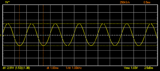 |
| TP4 signal after first triode anode 2910mVpp. Gain 1 = 0.5 (13.6 dB) |
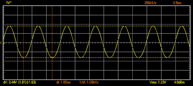 |
| TP4 signal after first triode anode 3440mVpp. Gain 1 = 1.0 (13.6 dB) |
 |
| C16 signal after second JFET buffer 3440mVpp. Gain 1 = 1.0 (0 dB) |
 |
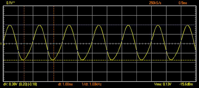
| C20 signal after 3-band equalizer 450mVpp. Gain = 1.0, Treble=Middle=Bass = 0.5 (-17.7 dB) |
 |
| TP21 signal after third JFET buffer 380mVpp (-1.5 dB) |
 |
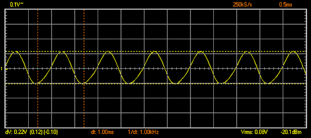
| TP5 signal after second triode anode 2170mVpp (15.1 dB) |
 |
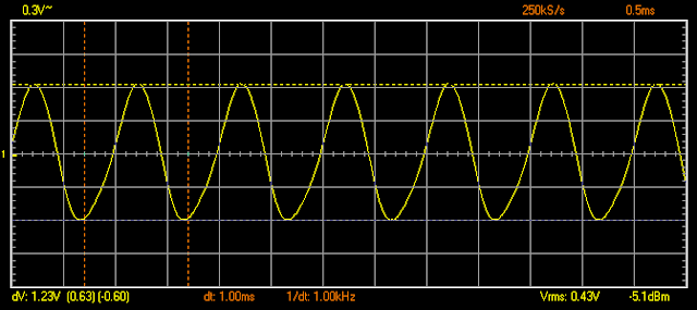
| C27 signal after fourth JFET amplifier 220mV, Gain 2 = 0 (-20 dB) |
 |
| C27 signal after fourth JFET amplifier 1230mV, Gain 2 = 0.5 (-5 dB) |
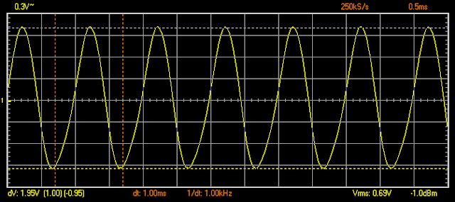 |
| C27 signal after fourth JFET amplifier 1950mV, Gain 2 = 1.0 (-1 dB) |
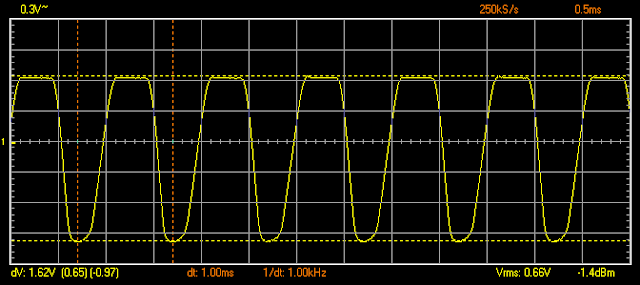 |
| C27 signal after fourth JFET amplifier 1620mV, Gain 2 = 0.0. BOOST ON (-2.5 dB) |
 |
| C27 signal after fourth JFET amplifier 8810mV, Gain 2 = 0.5. BOOST ON (12.2 dB) |
 |
| C27 signal after fourth JFET amplifier 12750mV, Gain 2 = 1.0. BOOST ON (15.4 dB) |
Saturday 29 July 2017
Korg Nutube 6P1 vs 12AX7 tube: Hybrid Amplifier (3)
Korg Nutube 6P1/12AX7 Hybrid Amplifier Schematics
Schematics are implemented using Eagle CAD 6.5. Circuit is compatible with Korg NuTube 6P1 triode and 12AU7/12AX7 triode valves by changing assembly options.
Eagle CAD 6.3.0 files and BoM can be found here:
Eagle CAD 6.3.0 files and BoM can be found here:
Page 1 shows input preamp. The circuit consists of the following stages:
- 1. Input dual JFET buffer/ amplifier with gain 1 control
- 2a. First NuTube triode amplifier with load 1 and Bias control
- 2b. First 12AU7 triode amplifier with gain 1 control
- 3. Second dual JFET buffer
- 4. 3-band equalizer (Fender tone stack)
- 5. Third JFET buffer
- 6a. Second Nutbe triode amplifier with load 2 and Bias control
- 6b. Second 12AU7 triode amplifier
- 7. Fourth dual JFET amplifier with Gain 2 control and Boost switch
NuTube 6P1 grid Bias can be controlled via RV3 trimmer from 0 to 3.4V, optimal value is obtained between 0.4-0.5.
Both triode filaments are powered by a +5V DC/DC converter, 240R resistors control the filament current on NuTube triode.
VR1-VR2 trimmers allow to change Nutube triodes anode load. Optimal value is obtained at 0.5-0.7.
RV2 attenuation trimmer is optional, normally not connected.
Page 2 consists of the following sections:
It is very important to add a 100K pull-up on AVCC pin 14, because the +24V power-on ramp can be very abrupt (>10V/ms) since it is controlled by a switch, if this pull-up is not added, power amp will be damaged.
There are independent volume controls for Power Amp, Headphones/Line-Out.
It is recommended to turn down the corresponding volume control before switching on the Boost, since a capacitor is connected abruptly and can generate loud pops, maybe a low value resistor added in series with the switch and capacitor could avoid this.
JP1-JP2 can change the gain of the power amp, if they are not installed gain is set to maximum.
RV10 allows to set power limit on power amp.
RV8 is the power amp volume control, it can be very loud if set to maximum. A series resistor could be added to reduce loudness.
A similar thing happens to RV9 Headphones/Line Out volume control
Page 3 consists of the following sections:
It is important to use a clean external AC/DC supply with switching frequencies out of the audible spectrum (>50kHz switching frequency recommended). A 100uH + 2x100uF input filter is used but frequencies lower than 1kHz are difficult to filter out.
The +24V to +5V DC/DC converter is used to power the heating filament for both Nutube 6P1 and 12AX7 tube and the headphones amplifier. Heater voltage for 12AX7 tubes is specified at +6.3VDC but 5V works well in starving mode.
Two +24V and +5V power on switches have been added, +24V power-on switch works as a standby control so that heater (+5V power-on switch) can be powered-on before the amp is powered. the inverse sequence should be respected when powering-off.
For NuTube 6P1 this powering on sequence is not required.
A blue/orange LED (NuTube/12AX7 use different colours) on the left shows when +24V power is active.
A green/orange LED on the right shows when +5V heater power is active.
Most of the power is dissipated by the Class-D power amp (25W), the heater + headphones amp dissipates less than 2.4W, and the preamplifier circuit 15mW, for a total of 28W max.
 |
| Schematics page 1/3: Input preamp |
- TI TPA3112D1 25W class-D Audio Power Amplifier
- TI TPA6111A2D 150mW headphones amplifier
- TI LME49723 dual opamp buffer for Headphones/Line-Out
It is very important to add a 100K pull-up on AVCC pin 14, because the +24V power-on ramp can be very abrupt (>10V/ms) since it is controlled by a switch, if this pull-up is not added, power amp will be damaged.
There are independent volume controls for Power Amp, Headphones/Line-Out.
It is recommended to turn down the corresponding volume control before switching on the Boost, since a capacitor is connected abruptly and can generate loud pops, maybe a low value resistor added in series with the switch and capacitor could avoid this.
JP1-JP2 can change the gain of the power amp, if they are not installed gain is set to maximum.
RV10 allows to set power limit on power amp.
RV8 is the power amp volume control, it can be very loud if set to maximum. A series resistor could be added to reduce loudness.
A similar thing happens to RV9 Headphones/Line Out volume control
 |
| Schematics Page 2/3: Class D 25W Power Amp, Headphones Amp, Line Out |
- +24V DC power input connector, filter and switch
- +24V to +5V DC/DC converter (0.5A)
- +24V ON LED, +5V ON LED
It is important to use a clean external AC/DC supply with switching frequencies out of the audible spectrum (>50kHz switching frequency recommended). A 100uH + 2x100uF input filter is used but frequencies lower than 1kHz are difficult to filter out.
The +24V to +5V DC/DC converter is used to power the heating filament for both Nutube 6P1 and 12AX7 tube and the headphones amplifier. Heater voltage for 12AX7 tubes is specified at +6.3VDC but 5V works well in starving mode.
Two +24V and +5V power on switches have been added, +24V power-on switch works as a standby control so that heater (+5V power-on switch) can be powered-on before the amp is powered. the inverse sequence should be respected when powering-off.
For NuTube 6P1 this powering on sequence is not required.
A blue/orange LED (NuTube/12AX7 use different colours) on the left shows when +24V power is active.
A green/orange LED on the right shows when +5V heater power is active.
Most of the power is dissipated by the Class-D power amp (25W), the heater + headphones amp dissipates less than 2.4W, and the preamplifier circuit 15mW, for a total of 28W max.
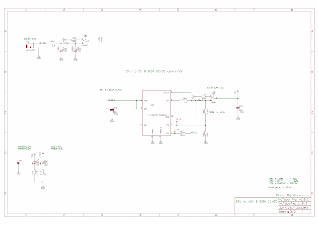 |
| Schematics 3/3: +24V to +5V @ 0.5A DC/DC converter |
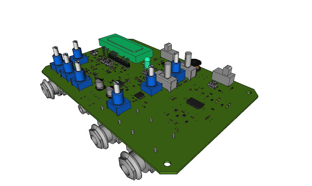
Korg Nutube 6P1/12AX7 Hybrid Amplifier PCB layout
A simple 2-side PCB board can support both hybrid amplifier versions NuTube/12AX7 by just using different assembly options.
 |
| PCB top layer |
 |
| PCB bottom layer |
Friday 9 June 2017
Tuesday 6 June 2017
Korg Nutube 6P1 vs 12AU7 tube: Hybrid Amplifier (1)
My next project is an Hybrid guitar amplifier: Triode preamp + Class D 25W amplifier.
FreeCAD 3D files can be found here:
FreeCAD 3D files can be found here:
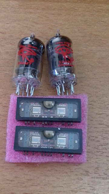
The preamp section can be populated with a Korg Nutube 6P1 triode
or alternatively a 12AU7 tubeThe amp is powered by an external AC/DC 24VDC out wall adapter.
It includes headphones, line out and 8 Ω speaker with 25W output.
Everyting is packed on a compact 1590J enclosure:
Labels:
12AU7,
1590J,
class-D,
hypbrid amp,
Korg NuTube,
Triode,
Tube
Friday 26 May 2017
Korg NuTube 6P1 vs 12AX7 starved tube / valve: Gain and frequency response
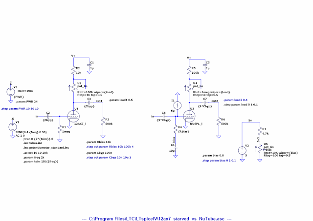
The following figure shows the Schematics used to compare the frequency response of NuTube 6P1 vs 12AX7 in starved mode:
12AX7 has a 1M pulldown on grid input while NuTube 6P1 has a bias circuit to adjust the bias voltage on the grid between 0V and 3.3V, connected to the grid via 33K series resistor, the typical grid current of 6uA has been added, since the model does not include this bias current.
Anode/plate output resistor load is 500K in both circuits.
Both circuits have anode/plate connected to +24V via a series resistor and a potentiometer to adjust load.
NuTube 6P1 has resistor values multiplied by 10 to be able to sweep around the maximum gain point.
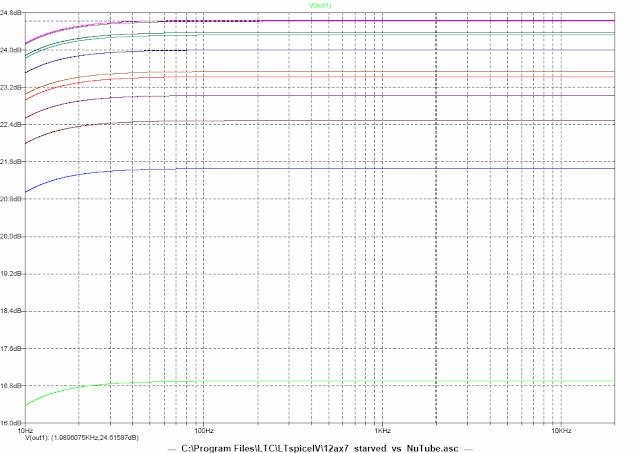
The following figure shows the starved 12AX7 frequency response between 10 Hz and 20 kHz with anode load potentiometer varying from 0 to 1. A maximum gain of 24.6 dB is obtained with a load resistance of 50K
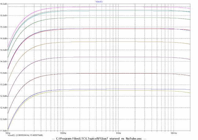
The following figure shows the NuTube 6P1 frequency response between 10 Hz and 20 kHz with anode load potentiometer varying from 0 to 1. A maximum gain of 15.9 dB is obtained with a load resistance of 400K.
NuTube 6P1 application note shows a gain of 14dB with anode powered at +12V and 17 dB with anode powered at +30V, which actually corresponds to simulations.
Bypass capacitors are also compared between 10nF and 10uF. NuTube 6P1 bypass capacitor value must be multiplied by 15 in order to have a similar response at lower frequencies:
Labels:
gain,
Korg NuTube,
starved 12AX7,
Triode,
Tube,
valve
Subscribe to:
Posts (Atom)
