Google statistics

Showing posts with label distortion. Show all posts

Monday, 10 April 2023

All Overdrive/Distortion effects pedals in one... or most of them

Inception and Inspiration (Analog Morphing Core)

Recently I came up with a technology used on Kernom RIDGE overdrive pedal called Analog Morphing Core. This technology uses a single knob called MOOD, that can be seen in action in this link and the pciture below. It allows to change the shape of the signal going from a pure sinewave, to soft clipped asymmetric, then symmetric, then hard clipped asymmetric, then symmetric.

Additionally, this pedal includes PRE TONE and POST TONE knobs that allow to change and equalize the tone before and after the clipping stage.

I think that Analog Morphing Core technology must require some digital processing in order to use a single control knob to modify several resistance values in the clipping circuit. Digitially controlled potentiometers maybe? I don't know.

My goal was not to acquirately emulate the exact behaviour of this complex pedal, that probably required thousands of hours for its development, but I liked the idea of being able to generate hard / soft, symmetric / asymmetric clipping, and also the idea to be able to change the tone before and after the clipping.

So I decided to design and make a guitar pedal circuit that was able to include all these different functions: Pre-Equalizer (PreEq), Gain (G), Soft Clipping (SC), Hard Clipping (HC), Post-Equalizer (PostEq) and Volume.

Kernom RIDGE is a quite complex piece of equipment but I decided to go for simplicity using analog potentiometers... but is it really less complex? 

Actually controlling all these function requires using lots of potentiometers, 12 in total!!:

3x 100kB for PreEq

3x 100kB for PostEq

1x 500kB for Gain

2x 10kB for Soft Clipping

2x 100RB for Hard Clipping

1x 100kA for Volume

Circuit Design and Simulation

For circuit design and simulation I use LTSpice. I will need a minimum of 3 opamps: one for PreEQ, one for Gain / Soft Clipping, and one for PostEQ, if I use two dual opamps, there is one left to be used as input unty gain buffer.

Equalizer

Pre and Post Equalizer will be identical circuits based on an opamp with Bass, Mids and Treble circuits:


Equalizer simulation, PreEQ + PostEQ Bass response:


Equalizer simulation, PreEQ + PostEQ Mid response:


Equalizer simulation, PreEQ + PostEQ Treble response:


Clipping section

An opamp soft clipping section followed by a hard clipping section. Schottky diodes (BAT54 or similar) used as clipping diodes:


Gain frequency simulation with no PreEQ, no PostEQ. 20 dB gain:


Gain transient simulation with no clipping:


Asymmetric soft clipping transient simulation at max gain:


Asymmetric hard clipping transient simulation at max gain and max soft clipping:
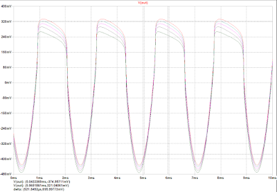

Symmetric hard clipping transient simulation at max gain and max soft clipping


Implementation

I used Eagle for schematics design:

Usually I design the PCB layout with Eagle and then I send the files to a PCB manufacturer, but this time I wanted to go "simple", at the end of the day the PCB is quite small and simple, but there will be many wires going from PCB to potentiometers. I decided to use bare board vith no copper, glue SMD components on the PCB and solder wires between components, and between components and potentiometers / connectors.

This is the bare PCB with components glued in, quite simple isn't it?


Well actually it was quite a nightmare to solder the wires, I had to be very quick and precise because if the component gets hot, the super glue will melt.
I used 30AWG wire wrap cable with one solid wire and thin insulation as this one 

I then used hot glue to fix the wires and avoid breaking the thin wires sue to tensions during installation.
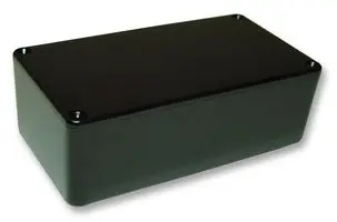
Usually I use Hammond type die cast aluminum boxes 1590B or 1590N1, which I personally prefer because it provides a bit more space, but this time I needed a bigger box to fit 12 potentiometers, the footswitch and an LED. I found a black ABS plastic box MB8 150 x 80 x 50mm that was just the side needed.
With all these simplifications, wasn't I risking to have poor shielding and being susceptible to get external noise and hum? Ususally a 2 sided PCB allows to have a full ground plane on bottom layer, so that all signals have good grounding and reference, But using wires I risked to create current ground loops that could capture external noise. The metal box is grounded and provides good shielding, but a plastic box can be exposed to external noise and capture 50 Hz hum, specially on a high gain pedal.

I added copper tape on bottom side of bare PCB connected to ground to try to improve grounding and shielding, and I was not sure I would need to internally shield the plastic box with copper or aluminum tape. At the end this was not needed and the pedal is not noisy.

I do not include pictures of the wired pedal because is quite messy and not very elegant or aesthetic.

I was worried to break the thin wire wrap wires and was extremely careful when assemblying the pedal, but the hot glue provided enough robustness to support tensions and bendings. 

Below a picture of the assembled and powered pedal. The 8 potentiometers on the left are 16mm diameter and had to be misaligned to be able to fit the in the box. 


I haven't yet labelled the knobs, which it is probably recommended on a pedal with so many knobs.

Test

PreEQ +PostEQ frequency response

PreEQ frequency response


PostEQ frequency response

No Gain time response

SC1 at max
SC1 and SC2 at max

SC2 at max:

Gain at max:
Gain and HC1 at max:

Gain, HC1 and HC2 at max:

Gain and HC2 at max:

Gain, HC1, HC2, SC1, and SC2 at max

Gain, HC1 and SC1 at max:

Bypass:

I am very satisfied with the sound and the possibilities of this pedal, maybe too many tweaking knobs but it has a wide range of sounds from boost to overdrive to quite hard distortion without entering into fuzz zone. The pre and post equalizer allow to shape the tone as desired, compressing or increasing mids, providing more brightness or top end or making it sound fatter.


Wednesday, 1 July 2015

DMFX-1: Open Source Digital Multi-Effects guitar pedal (1)

Rezzonics© presents the most compact digital multi-effects guitar pedal, completely open source, giving you the opportunity to create your own stereo effects or use a huge range of pre-programmed effects.

Every analog or digital effect your guitar needs in one compact format. The best of both worlds: ANALOG for overdrive, distortion, fuzz, octave-up, DIGITAL for echo, delay, chorus, tremolo, phaser, flanger... and many others you can imagine: looper, pitch shift, reverb, leslie...

DMFX-1 main features:
  • TI C55x 16-bit fixed point DSP, providing quality, low power and low cost
  • Dual DSP for low latency, real time signal processing and fully independent Audio and Control processing.
  • Up to two SD/MMC cards for Software and audio data storage
  • One graphical LCD 128x32 pixels Blue with White LED backlight for better visibility
  • Up to 5 configurable LEDs
  • One 5-button display navigator for seamless effect configuration
  • Up to five digitally controlled and configurable potentiometers
  • Analog configurable input distortion (overdrive, crunch, vintage, fuzz...)
  • Analog octave-up effect, mixable with distortion
  • Dual Mono L/R Line Output
  • Stereo Headphones output
  • Guitar Mono Line input
  • Analog input / output buffers and filters
  • Standard +9V DC or USB +5V DC power input
  • Up to 2x USB 2.0 ports (Audio, Control) for PC connectivity
  • Optional USB debugging port XDS100v2, TI Code Composer Studio compatible
  • Foot switch input
  • Compact size: 130 mm x 110 mm x 32 mm (W x D x H)
A stand-alone unit: just plug your guitar, your headphones and configure your desired effect easily via the navigator and LCD menus.

Stereo effects like reverb or speaker rotating effects like leslie can be emulated thanks to the dual mono and stereo outputs.

Analog feel can be emulated thanks to five configurable potentiomenters digitally controlled.

JFET buffer input, low THD distortion, low-voltage, rail-to-rail audio opamps and filters to better adapt guitar signal input and reduce input noise. Exclusive low-cost Schottky diode distortion circuits that emulate germanium clipping diodes.

Analog support for Tuner and Noise compression.

One graphical LCD 128x32 pixels Blue with White LED backlight for better visibility in dark places. A 5-buttons navigator (up-down-left-right-OK) allows easy navigation and effect configuration through menus.

One dedicated audio DSP and one dedicated control DSP provide low latency and real time, while reducing the bill of materials. Control DSP is used for status / commands operations: LCD, buttons and potentiometer control, while Audio DSP is fully dedicated to real time audio effects.

Up to two USB 2.0 (type Mini-B) interfaces allow pedal connection to a PC, for command / status or audio exchange.

Up to two SD/MMC cards can be connected to audio DSP for huge program and audio data storage.

One additional USB (Type-B) interface allows JTAG-Boundary Scan DSP debugging using TI XDS100v2 and Code Composer Studio for implementing your DSP effects.

Open source libraries will offer free digital effect exchange and improvement.

Several assembly options for low cost and high performance scalability.

DMFX-1 is low power, it can be powered by batteries, external +9V DC-DC converter or USB port.

DMFX-1 is compact: Main board + mezzanine board can be packed on a 148 mm x 100 mm x 24 mm enclosure (W x D x H)


Compact size: 148 mm x 100 mm x 24 mm (W x D x H)
3D view of the 2 PCB DMFX-1 guitar pedal (image created with FreeCAD)
DMFX-1 front view showing connectors

DMFX-1 rear view showing USB connectors


DMFX-1 block diagram

COMING SOON!!
STAY TUNED!!

Wednesday, 5 February 2014

Tube Simulator - Simulations - End stage amplifier (2/3)

End stage amplifier simulations

The figure below shows the schematics of the VoxAC30 end stage amplifier. It starts with a 2-band equalizer for bass and treble and a switch  for equalization shift that adds a deeper notch in the mid tones when activated.

It is followed by an amplification stage based on two 12AX7A valves. It is a valve version of a differential amplifier. It is followed by the high power end stage amplifier based on 4 EL84 valves that feeds the audio transformer and the speaker.


The figure below shows the schematics of the Tube Simulator end stage amplifier. It starts with an almost identical 2-band equalizer, where the values have been scaled to have the same frequency response but more reasonable values. Capacitor values have been multiplied by 100, from 56 pF to 5.6 nF and 22 nF becomes 2.2 uF. Resistor values have been divided by 100 to keep the RC ratio and the same frequency response, so 100 kohm becomes 1 kohm, 10 kohm becomes 100 ohm, and the 1 Mohm potentiometer become 10 kohm. The 2-band equalizer is followed by an RC high pass filter (100 nF, 24 kohm)

The Tube Simulator end stage amplifier consists also of two amplifier sections but opamp based.
Unity gain opamp amplifiers are used to separate each section. Unity gain has been used instead of followers to allow some gain adjusting between sections if required.
The first opamp section includes soft clipping based on silicon diodes plus negative clipping based on germanium plus a series resistor. Another RC high pass filter is added afterwards.

The second opamp section includes soft clipping based on silicon diodes followed by another RC high pass filter.


The following plot compares the time response of a 400Hz sinusoid exponentially decreasing with 50Hz time constant after the 2-band equalizer (top plot), first amplifier section (middle plot) and second amplifier section (bottom plot) of the end stage amplifier for tube simulator (green trace) and AC30 valve amp (red trace).
Different voltage levels have been scaled for comparison.


The following plot shows frequency response from 10 Hz to 20 kHz . Frequency response of Tube Simulator matches that of Vox AC30 amplifier. Different voltage levels have been scaled for comparison.

Tuesday, 4 February 2014

Tube Simulator - Simulations - Preamp (1/3)

This work is based on Stephan Möller Vox AC30 Amplifier Simulator. It is basically a reverse engineering of his work, so it is fair to start by giving credit to his amazing work. Some schematics can be found on the internet with incomplete component values.
It consists of three stages:
  • Preamplifier
  • End stage amplifier
  • Speaker Simulator
In order to implement a reverse engineering of this project I created an LTSPice simulation of a simplified version of the real VOX AC30 amplifier and an equivalent LTSpice simulation of the tube simulator. I tried to adjust the component values in order to obtain a similar time and frequency response in both circuits for each stage.

Let's start with the Preamplifier stage.

The Preamplifier stage

The Vox AC30 preamplifier consists of two valve amplifier stages, a first stage with one 12AX70 valve followed by a second stage with two 12AX70 valves with a gain potentiometer between both amplifier stages.
These are the schematics for the Vox AC30 preamplifier:

The Tube Simulator preamplifier also consists of two amplifier stages but opamp based and a gain potentiometer between them.
The first opamp stage includes soft clipping based on zener diodes in the opamp feedback with different voltage values to provide some unbalanced clipping or saturation at positive and negative values. I found that a 6.2V and a 4.3V zener where more adequate to match VOX AC30 response. Between the opamp and the gain potentiometer there is a positive hard cliping section based on a Schottky diode with a series resistor. A high value of 470K is used that quite mitigates the diode clipping. This part is quite tricky because actually does not match valve response but having an important clipping affected negatively the next stages.

The second opamp stage includes 4 different types of soft clipping blocks:
Two blocks (positive/negative) based on 2.7V zener diodes + silicon diode in series (not sure the silicon diodes are any useful here) + series resistor (470 ohms / 10 Kohms)
One block based on a germanium diode + series resistor (91 Kohms)
One block based on a 2N2907 PNP transistor with biased base (Rq1 = 47 kohms). Real implementation of the bias will be explained later in the pratical implemention of the circuit.

The figure below shows the schematics of the Tube Simulator preamp:
The following plot compares the time response of a 500Hz sinusoid exponentially decreasing with 50Hz time constant after the first (top plot) and second (bottom plot) stage of the preamplifier for tube simulator (green trace) and AC30 valve amp (red trace). This is a bit tricky, but positive clipping is reduced in the tube simulator for a better stability and signal matching in the next amplifier stage. Voltage levels are higher in the valve amp, so signals are scaled for comparison.
 As it can be observed in the next figure frequency response from 10 Hz to 20 kHz matches very closely.

Sunday, 26 January 2014

Germanium diodes vs Schottky diodes for audio distortion

Germanium diodes are a preferred choice for use in distortion guitar pedals for their unique sounding characteristics when clipping an audio signal. Germanium clipping is softer than that of regular rectifier silicon diodes but clipping starts at lower levels. A softer clipping generates less high frequency harmonics and hence it produces a warmer sound. But the main characteristics that provide a more agreeable sound to the ears, like that found on valves, come from even harmonics, and that cannot be achieved with symmetric clipping but asymmetric clippping.

Germanium diodes also have a lower forward voltage than silicon diodes and hence they are able to clip signals at lower levels than silicon diodes.

But unfortunately, germanium diodes are scarce an expensive these days since their use as rectifiers in electronics is quite reduced and they have been displaced by a variety of different types of diodes made out of silicon. Regular silicon diode rectifiers have an abrupt I-V curve more adequate for rectification purposes, which translates in a hard clipping of the signal at approximately 600mV. On the other hand, Germanium diodes have a much less abrupt I-V curve which means that they provide a much softer clipping that starts at approximately 300mV.

Germanium diodes (like 1N34A) are hard to find in usual large distributors such as Digikey, Mouser, Newark, Farnell or RS, they are mostly found in specialised audio and guitar pedal boutiques since their use is more and more reduced to audio distortion in fuzz pedals. They are only found in conventional through-hole mounting (glass DO-7 package) but not in SMD packages.
The 1N34A can be found from 0.4€ to 1.71$ in a glass DO-7 package.


Schottky diodes (like BAT54) are a special but quite common type of silicon diodes used as rectifiers with very low forward voltage 200mV, similar to that of germanium diodes, but they also show a very abrupt I-V curve that generates hard clipping at a much lower voltage than regular silicon diodes. They can be found in many different packages including small SMD packages with the advantage that two diodes can be included in the same package, reducing BoM costs additionally. The BAT54S can be found as cheap as 0.022$ in SOT-23 SMD package.


In order to be able to replace Germanium diodes by Schottky diodes and reduce the steep ramp it only requires adding a resistor in series with the diode so that an increasing voltage drop is added with an increasing current. Using a variable resistor o potentiometer can additionally provide control on the clipping softness, higher resistor value means more clipping softness.

The figure below shows the schematics used with LTSpice simulator in order to compare the I-V and V-I curves of the most common germanium diode (1N34A) with a quite common and cheap Schottky diode (BAT54).

LTSpice schematic file

The schematics with diodes in series allows comparing voltage drop in both cases: Germanium vs Schottky + series resistor for a given range of current. Simulation is repeated for Schottky diode with different resistor values. Series resistor is entered as parameter Rx from 5 to 500 ohms.

The schematics with diodes in parallel allows comparing current through the diodes in both cases for a given range of input voltage and for different resistor values.

The figure below shows the resulting I-V curves with V ranging from 0V to 1V and current from 0mA to 90mA.

The red curve shows the I-V curve of the Germanium diode while green curves show the I-V curve for Schottky diode with different values of series resistor from 5 ohms to 500 ohms, the higher the resistor value the flatter the curve.
As it can be seen, there is no way to exactly replicate the germanium diode curve with a Schottky diode, but the Schottky diode may actually provide softer curves than the germanium diode which is the main purpose of using germanium diodes. For low values of current, the resistor must be higher in order to overlap the germanium curve, when current increases, the resistor must be lower, for 5 ohms both curves run parallel showing an asymptote or convergence in the infinity.

The figure below shows the V-I curves with current ranging from 0mA to 1mA and voltages ranging from 0 to 600mV.

At very low current values the voltage curves overlap for highest resistor value (500 ohms), but at higher current values the voltage curves overlap for 67 to 80 ohms.

Let's see the effects of both diodes in a real simulation using soft clipping and hard clipping configurations.
The schematics below show a circuit with both types of diodes using a soft clipping section followed by a hard clipping section.

LTSpice schematic file
Opamp PSpice model library

The soft clipping section consists of an opamp amplifying ten times the input signal. Soft clipping diodes are added in both directions (for positive and negative clipping) in the opamp feedback circuit between the negative input and the output of the opamp. The chosen reference resistor (Rin) between negative opamp input and ground is 10 kohms. The feedback resistor is 100 kohm for a x10 gain of the opamp. Varying this 10k value may require adjusting the series resistor of the Schottky diodes to match germanium diode response. The series resistor value required to match germanium diode response in this case is 250 ohms.

The hard clipping section consists of two diodes in both directions between the output of the opamp and ground after a decoupling capacitor of 4.7uF. The series resistor value required to match germanium diode response in this case is 14 ohms.

Figure below shows soft clipping signal comparison for germanium (green) and Schottky (red) for an input sinusoidal signal of 440Hz and 600mV and series resistor values of 5, 25, 100, 250 and 500 ohms. Soft clipping signal in this simulation is probed between the opamp negative input and the opamp output. As it can be seen, Schottky signal (in red) is in general lower than germanium signal (in green) for most resistor values except for 500 ohms, but the waveform shape seems closer to germanium waveform for 250 ohms.

Figure below shows hard clipping signal comparison for germanium (green) and Schottky (red) for an input sinusoidal signal of 440Hz and 600mV and series resistor values of 5, 10, 15 and 20 ohms. Hard clipping in this simulation is probed between the signal connecting output decoupling cap and diodes, and GND. Schottky signal (in red) is closer to germanium signal (in green) for a series resitor value of 15 ohms.
The figure below shows the time response signal in mV for both soft clipping (top plot) and hard clipping (bottom plot) respectively. The input is a sinusoidal signal of 440 Hz that starts at 1V and exponentially decreases with a time constant of 30 Hz.

The use of a exponentially decreasing signal is chosen to recreate the response to a real audio signal source with different voltage levels from 1V to several tens of mV. Clipping is higher for higher voltage levels. The choice of Schottky and Germanium diodes also allows clipping starting at lower voltage levels (200 to 300 mV) compared to silicon (500 to 600mV) or LED (>1200mV) diodes.

The figure below shows the FFT signal (frequency domain spectrum) in dB between 300 Hz and 30kHz for soft clipping (top plot) and hard clipping (bottom plot) signals respectively using a Blackman window to soften the signals and enhance harmonics visibility.

As it can be seen, frequency spectrum for both types of diodes (germanium and Schottky) are very similar and almost overlap perfectly.
Soft clipping shows less high frequency harmonics (warmer sound) which is more suitable for overdrive distortion while hard clipping shows high frequency harmonics (harsher sound) more suitable for fuzz distortion.

Conclusion

Spice simulations show that germanium diodes can be replaced by Schottky diodes plus series resistor for distortion applications with almost no difference in the waveform signals obtained.
But these simulations must be completed with real life experiments to confirm simulation results.

I plan to implement a version of the famous and noisy Shin-Ei Fuzz-Wah with the option of germanium or Schottky diodes for comparison. Stay tuned to my blog for Spice simulations of this pedal and real implementation of it.

Notes

The figure below shows the I-V curve at near zero current for Germanium diode (red curve) and Schottky + Rseries (magenta curve). Zero bias resistance is the value of the slope of the previous curve (Rbias=dV/dI) at 0A. Using a function dependent current source (BI in LTSpice) I could simulate a current whose value is the derivative of voltage respect current for the Germanium diode (green curve) and the Schottky + Rseries (cyan curve). The value at 0A is the zero bias resistance, which is 167 Kohm for germanium diode and 257 Kohm for Schottky +Rseries.

Zero bias impedance and I-V curve at near zero current