Google statistics

Showing posts with label overdrive. Show all posts

Monday, 10 April 2023

All Overdrive/Distortion effects pedals in one... or most of them

Inception and Inspiration (Analog Morphing Core)

Recently I came up with a technology used on Kernom RIDGE overdrive pedal called Analog Morphing Core. This technology uses a single knob called MOOD, that can be seen in action in this link and the pciture below. It allows to change the shape of the signal going from a pure sinewave, to soft clipped asymmetric, then symmetric, then hard clipped asymmetric, then symmetric.

Additionally, this pedal includes PRE TONE and POST TONE knobs that allow to change and equalize the tone before and after the clipping stage.

I think that Analog Morphing Core technology must require some digital processing in order to use a single control knob to modify several resistance values in the clipping circuit. Digitially controlled potentiometers maybe? I don't know.

My goal was not to acquirately emulate the exact behaviour of this complex pedal, that probably required thousands of hours for its development, but I liked the idea of being able to generate hard / soft, symmetric / asymmetric clipping, and also the idea to be able to change the tone before and after the clipping.

So I decided to design and make a guitar pedal circuit that was able to include all these different functions: Pre-Equalizer (PreEq), Gain (G), Soft Clipping (SC), Hard Clipping (HC), Post-Equalizer (PostEq) and Volume.

Kernom RIDGE is a quite complex piece of equipment but I decided to go for simplicity using analog potentiometers... but is it really less complex? 

Actually controlling all these function requires using lots of potentiometers, 12 in total!!:

3x 100kB for PreEq

3x 100kB for PostEq

1x 500kB for Gain

2x 10kB for Soft Clipping

2x 100RB for Hard Clipping

1x 100kA for Volume

Circuit Design and Simulation

For circuit design and simulation I use LTSpice. I will need a minimum of 3 opamps: one for PreEQ, one for Gain / Soft Clipping, and one for PostEQ, if I use two dual opamps, there is one left to be used as input unty gain buffer.

Equalizer

Pre and Post Equalizer will be identical circuits based on an opamp with Bass, Mids and Treble circuits:


Equalizer simulation, PreEQ + PostEQ Bass response:


Equalizer simulation, PreEQ + PostEQ Mid response:


Equalizer simulation, PreEQ + PostEQ Treble response:


Clipping section

An opamp soft clipping section followed by a hard clipping section. Schottky diodes (BAT54 or similar) used as clipping diodes:


Gain frequency simulation with no PreEQ, no PostEQ. 20 dB gain:


Gain transient simulation with no clipping:


Asymmetric soft clipping transient simulation at max gain:


Asymmetric hard clipping transient simulation at max gain and max soft clipping:


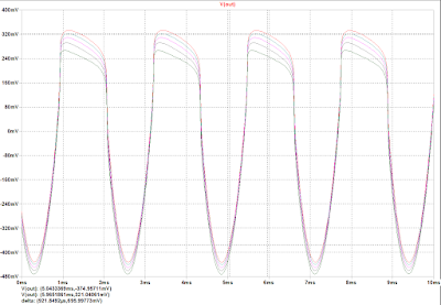
Symmetric hard clipping transient simulation at max gain and max soft clipping


Implementation

I used Eagle for schematics design:

Usually I design the PCB layout with Eagle and then I send the files to a PCB manufacturer, but this time I wanted to go "simple", at the end of the day the PCB is quite small and simple, but there will be many wires going from PCB to potentiometers. I decided to use bare board vith no copper, glue SMD components on the PCB and solder wires between components, and between components and potentiometers / connectors.

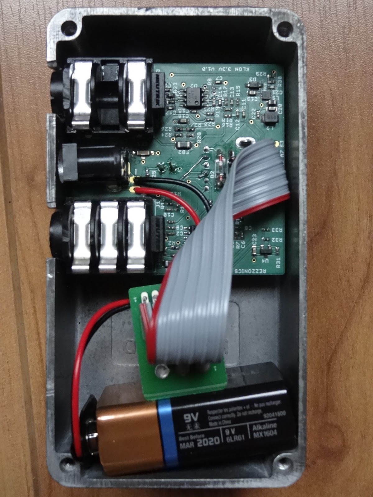
This is the bare PCB with components glued in, quite simple isn't it?


Well actually it was quite a nightmare to solder the wires, I had to be very quick and precise because if the component gets hot, the super glue will melt.
I used 30AWG wire wrap cable with one solid wire and thin insulation as this one 

I then used hot glue to fix the wires and avoid breaking the thin wires sue to tensions during installation.
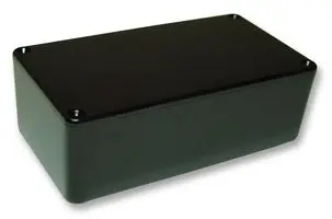
Usually I use Hammond type die cast aluminum boxes 1590B or 1590N1, which I personally prefer because it provides a bit more space, but this time I needed a bigger box to fit 12 potentiometers, the footswitch and an LED. I found a black ABS plastic box MB8 150 x 80 x 50mm that was just the side needed.

With all these simplifications, wasn't I risking to have poor shielding and being susceptible to get external noise and hum? Ususally a 2 sided PCB allows to have a full ground plane on bottom layer, so that all signals have good grounding and reference, But using wires I risked to create current ground loops that could capture external noise. The metal box is grounded and provides good shielding, but a plastic box can be exposed to external noise and capture 50 Hz hum, specially on a high gain pedal.

I added copper tape on bottom side of bare PCB connected to ground to try to improve grounding and shielding, and I was not sure I would need to internally shield the plastic box with copper or aluminum tape. At the end this was not needed and the pedal is not noisy.

I do not include pictures of the wired pedal because is quite messy and not very elegant or aesthetic.

I was worried to break the thin wire wrap wires and was extremely careful when assemblying the pedal, but the hot glue provided enough robustness to support tensions and bendings. 

Below a picture of the assembled and powered pedal. The 8 potentiometers on the left are 16mm diameter and had to be misaligned to be able to fit the in the box. 


I haven't yet labelled the knobs, which it is probably recommended on a pedal with so many knobs.

Test

PreEQ +PostEQ frequency response

PreEQ frequency response


PostEQ frequency response

No Gain time response

SC1 at max
SC1 and SC2 at max

SC2 at max:

Gain at max:
Gain and HC1 at max:

Gain, HC1 and HC2 at max:

Gain and HC2 at max:

Gain, HC1, HC2, SC1, and SC2 at max

Gain, HC1 and SC1 at max:

Bypass:

I am very satisfied with the sound and the possibilities of this pedal, maybe too many tweaking knobs but it has a wide range of sounds from boost to overdrive to quite hard distortion without entering into fuzz zone. The pre and post equalizer allow to shape the tone as desired, compressing or increasing mids, providing more brightness or top end or making it sound fatter.


Sunday, 18 September 2016

Klon 3v3 clone: assembly and test

PCB Assembly

Circuit has been assembled on a 54 x 54 mm 2-layer PCB that fits into a 1590B enclosure.
Most components except 1N34A germanium diodes are SMD, with mainly 0402 passives. Phone jack connectors, DC jack connector, 9mm potentiometers and 5mm T1-3/4 LED are through-hole PCB mounted in order to minimize cabling. A 6-wire flat cable connects main to PCB 3-SPDT footswitch mounted on another small PCB. 9V battery clip is connected by 2 wires on +/- pads near the DC jack
Clean PCB before assembly
Main ICs (opamps, DC-DC converter, voltage reference) are assembled first using solder paste and a hot air soldering station
Main ICs already assembled
Passive and discrete components (ferrites, EMI filter, diodes, inductors, capacitors, resistors), mostly 0402, are then assembled using solder paste and hot air station.
PCB view with all SMD components assembled
Through-hole components on bottom side (actually this side faces up): 9mm potentiometers and 5mm LED are then soldered using an iron and soldering wire:
Klon 3v3 clone PCB bottom layer assembled
Through-hole components on top side: germanium diodes, phone jack connectors, DC jack connector are soldered using soldering wire and iron
Klon 3v3 clone PCB top layer assembled
Once the circuit was fully assembled it seemed to fit well on the 1590B enclosure, but actually screwposts didn't allow the PCB border to touch the top enclosure sidewall so that DC jack would be receded probably avoiding proper DC plugging.
Components fitting on 1590B enclosure
The PCB was finally mounted with connectors on one enclosure side. Next time PCB corners will have to be chamfered and connectors placed closer to the center in order to mount it with connectors on top side of the enclosure.
Klone 3v3 clone fully assembled

Enclosure design and build

For the enclosure design I decided to use the etching technique. It was my second attempt and the results were not quite satisfactory.
Enclosure design was made using InkScape. A Star Wars trooper color image was converted to black and white, then inverted and mirrored, printed on a PNP blue paper with a laser printer and ironed on a previously sanded and polished enclosure. 


Enclosure design made using Inkscape
PNP transfer was a complete disaster so I finally used satin paper. Defaults were corrected with a permanent marker and etched
Enclosure view after PNP blue transfer (FAIL!!)
Etching was made using a mix of hydrogen peroxide and hydrochloric acid which I think it is actually too strong, I finally over-etched the design corroding more areas than I should. Permanent marker did not protected well the aluminium from acid attack. The final result was quite modest.
Klon 3v3 clone pedal finished
Plug it in and test!
Klon3v3 clone switched-on and ready for test

Electrical Test

For electrical test, a Velleman PCSGU250 oscilloscope and signal generator was used. Three different signals were used: a 300mVpp 440Hz sinewave, a 300mVpp 4kHz sinewave, and a 300mVpp 1kHz guitar string note sampled. Signal is injected in the guitar pedal input and signals are probed with oscilloscope in different parts of the circuit with different gain and treble settings (0-5-10): 
  • first buffer opamp output (out1a), 
  • second gain opamp output (out1b), 
  • clipping diodes output (clip), 
  • third opamp output (out2a) and 
  • fourth tone opamp output (out2b)
At 440Hz with gain set at maximum, the total gain of the circuit is >23, 17 and 10dB with treble set at 10, 5 and 0 respectively. Saturation happens with gain and treble set to 10 with an output signal that has 3.25Vpp.

At 4kHz with gain set at 10, the total gain of the circuit is 14, 1.8 and -7.7dB with treble set at 10, 5 and 0 respectively. At 4.4kHz and an input of 300mV, the maximum output level is 1.5Vpp.

With a 300mVpp 1kHz guitar string note signal the maximum level obtained is 2.6Vpp (15dB gain)
440Hz sinewave 300mVpp input
440Hw sinewave 1620mVpp gain amplifier output (gain=10, 15dB) (out1b)
440Hw sinewave 181mVpp gain amplifier output (gain=5, -4.2dB) (out1b)
440Hw sinewave 22mVpp gain amplifier output (gain=0, -23dB) (out1b)
440Hz sinewave 340mVpp clipped signal (gain=10, 1.2dB) (clip)
440Hz sinewave 260mVpp clipped signal (gain=0-5, -1.1dB) (clip)
440Hz sinewave 1490mVpp second opamp output (gain = 10, 14dB) (out2a)
440Hz sinewave 820mVpp second opamp output (gain = 5, 9dB) (out2a)
440Hz sinewave 540mVpp second opamp output (gain = 0, 5.2dB) (out2a)
440Hz sinewave 3250Vpp tone opamp (treble=10, gain=10, 22.6dB) (out2b)
440Hz sinewave 2130mVpp tone amp output (treble=5, gain=10, 17dB) (out2b)
440Hz sinewave 970mVpp tone amp output (treble=0, gain=10, 10dB) (out2b)
4.4kHz sinewave 2010mVpp gain amplifier output (gain=10, 16.6dB) (out1b)
4.4kHz sinewave 290mVpp gain amplifier output (gain=5, -0.23dB) (out1b)
4.4kHz sinewave 190mVpp gain amplifier output (gain=0, -3.73dB) (out1b)
4.4kHz sinewave 760mVpp clipped signal (gain=10, 8.4dB) (clip)
4.4kHz sinewave 280mVpp clipped signal (gain=5, -0.43dB) (clip)
4.4kHz sinewave 220mVpp clipped signal (gain=0, -2.53dB) (clip)
4.4kHz sinewave 280mVpp second opamp output (gain=10, -0.63dB) (out2a)
4.4kHz sinewave 112mVpp second opamp output (gain=5, -8.53dB) (out2a)
4.4kHz sinewave 60mVpp second opamp output (gain=0, -14dB) (out2a)
4.4kHz sinewave 1500mVpp tone amp output (treble=10, gain=10, 14dB) (out2b)
4.4kHz sinewave 370mVpp tone amp output (treble=5, gain=10, 1.8dB) (out2b)
4.4kHz sinewave 120mVpp tone amp output (treble=0, gain=10, -7.7dB) (out2b)
1kHz guitar note 280mVpp input
1kHz guitar note 39mVpp output (gain=0, treble=0, -18dB) (out2b)
1kHz guitar note 115mVpp output (gain=0, treble=5, -8.3dB) (out2b)
1kHz guitar note 480mVpp output (gain=0, treble=10, 2.4B) (out2b)
1kHz guitar note 76mVpp output (gain=5, treble=0, -11dB) (out2b)
1kHz guitar note 220mVpp output (gain=5, treble=5, -3.7dB) (out2b)
1kHz guitar note 970mVpp output (gain=5, treble=10, 8dB) (out2b)
1kHz guitar note 210mVpp output (gain=10, treble=0, -4.5dB) (out2b)
1kHz guitar note 710mVpp output (gain=10, treble=5, 4.6dB) (out2b)
1kHz guitar note 2590mVpp output (gain=10, treble=10, 15dB) (out2b)