Google statistics

Showing posts with label Korg NuTube. Show all posts

Tuesday, 1 May 2018

NuTube Overdrive - Spice simulations

Disclaimer

This is just an amateur pedal with no intention for profit or to infringe any trademark.
Tube Screamer is a trademark of Hoshino Gakki Co.
Nutube is a trademark of KORG INC.
This pedal is not for sale. If you want to buy a similar pedal I recommend you Ibanez NTS Screamer.

NuTube Overdrive Schematics

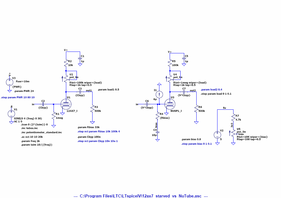
NuTube Overdrive is basically a Tube Screamer TS808 classic circuit (with a couple of mods I will explain later) where two NuTube triodes amplifier stages have been added between the preamp and the tone circuit, the original Tube Screamer output of the preamp is mixed with the output of the two triode amp sections by means of a 100K linear potentiometer, the buffered output of the mix is connected to the original tone circuit.

The following figure shows the LTSpice schematics of the NuTube Screamer pedal:
NuTube Screamer LTSpice schematics

NuTube Screamer Mods

The following mods have been made to the original schematics:
  1. Bass boost mod: 220nF capacitor added in parallel to 47nF on the high pass filter connected to the preamp section inverting input. This mod can be remove by just removing a series 0R resistor
  2. Tone mod: 20K tone potentiometer has been replaced by 5K linear potentiometer providing a more gradual response of the tone potentiometer.
  3. Asymmetric clipping: The original pedal had symmetric clipping, here an additional diode has been added in series to the positive output cycle.
  4. Output buffer: Resistor biasing has been slightly changed using 1000K resistor bridge from +9VDC instead of a 510K single resistor to +4.5VDC. It is basically the same.
Some components have been changed due to availability, performance or space gain:
  1. Original diodes were silicon MA150, they have been changed by dual BAV199 silicon diodes for space gain, and easier asymmetrical circuit construction.
  2. Original opamp JRC4558 has been replaced by LME49723 which has better performance in terms of harmonic distortion, noise, bandwidth, offset voltage and slew rate. See comparison here
  3. Original transistors 2SC1815 used for buffers  have been replaced by MMBT5089 in a small SOT23 package

Frequency response

The following figure shows the gain response from 0 to 10 with tone at 5 and mix at 10, maximum gain is 56 dB and minimum gain is 36 dB:
NuTube Screamer Gain = 0 to 10, Tone = 5, Mix = 10
The following figure shows tone response from 0 to 10 with gain at 10 and mix at 10:
NuTube Screamer Tone = 0 to 10, Gain = 10, Mix = 10
 The following figure shows Mix response from 0 to 10 with gain at 10 and tone at 5, maximum gain is 56 dB and minimum gain is 38 dB:
NuTube Screamer Mix = 0 to 10, Gain 10, Tone = 5
The total gain of NuTube triode amps section is 17.7dB, 8.2 dB for the first section, almost flat from 10 Hz to 20KHz (82mdB loss at 20 kHz) and 9.5dB for the second section (with 141dB loss at 20kHz)

Time response

Time response shows the pedal output signal with different settings with a 60 mVp-p 30s-1 decaying 440Hz sinewave input signal. Clipping is always on.

The following figure shows Gain response from 0 to 10 with Tone at 5 and Mix at 5:
NuTube Screamer time response with Gain = 0 to 10, Mix = 10, Tone = 5
The following figure shows Tone response from 0 to 10 with Gain at 10 and Mix at 5:
NuTube Screamer time response with Tone = 0 to 10, Mix = 5, Gain = 10
The following figure shows Mix response from 0 to 10 with Gain at 10 and Tone at 5:
NuTube Screamer time response with Mix = 0 to 10, Tone = 5, Gain = 10

Frequency response at +9V and +18V

The same circuit could be powered at +18V, to increase around 10dB the gain, here are the simulations at +9V and +18V
NuTube Screamer Freq response at +9V and +18V with Tone = 0 to 10, Gain = 10, Mix = 10


Sunday, 17 September 2017

Sunday, 30 July 2017

Korg Nutube 6P1 vs 12AX7 tube: Hybrid Amplifier (4)

Korg Nutube 6P1 Hybrid Amplifier circuit test and verification

Below a close picture of the Korg NuTube 6P1 powered on.

Korg Nutube 6P1
A picture of the whole board powered on.
Blue LED is +24V power on, greeen LED is +5V power on.Top sliding switch is +24V on/off, just below is the +5V on/off switch. To the right is the Gain Boost on/off for the power amp 8ohm speaker section, just below, the blue potentiometer, is the output gain control, below is the Gain Boost switch for the headphones/line-out section, below it is the power amp volume, below at the bottom is the headphones/line-out volume.
On the left at the bottom are the three controls for the 3-band equalizer, based on a Fender tone stack: bass, mid and trebles. Above the bass control is the input gain.
The 24-pins TSSOP device on the right is the 25W class-D power amplifier.
NuTube 6P1 is plugged into a 2mm pitch socket resting over 2 rubber bumpers to avoid vibrations that could pick microphonic noise.
Korg Nutube 6P1 Hybrid 25W Amplifier

Wave signal verification with oscilloscope

Summary of results:
  • First JFET amplifier gain with gain control 
    • G1=0.0 =>-2.7 dB
    • G1=0.5 =>  0.1 dB
    • G1=1.0 =>  1.6 dB
  • First NuTube 6P1 triode stage gain is 14dB
  • Second JFET buffer gain is 0dB
  • 3-band equalizer gain at 1kHz with Bass, Mid and Top = 0.5 is -18dB
  • Second NuTube 6P1 triode stage gain is 15dB
  • Third JFET amplifier gain with gain control and Boost Off:
    • G2=0.0 =>-20 dB
    • G2=0.5 => -5 dB
    • G2=1.0 => -1 dB
  • Third JFET amplifier gain with gain control and Boost ON:
    • G2=0.0 =>-2.5 dB
    • G2=0.5 => 12 dB
    • G2=1.0 => 15 dB
Maximum output level is 12750mVpp which corresponds to a maximum total gain of 26.5dB

Input signal: Sine wave 600mVpp 1kHz
A 1kHz sinewave 600mVpp is used at the input
TP2 signal after first JFET buffer 440 mVpp. Gain 1 = 0.0 (-2.7 dB)
TP2 signal after first JFET buffer 610 mVpp. Gain 1 = 0.5. (0.1 dB)
TP2 signal after first JFET buffer 720 mVpp. Gain 1 = 1.0 (1.6 dB)
TP4 signal after first triode anode 2180mVpp. Gain 1 = 0.0 (13.9 dB)
TP4 signal after first triode anode 2910mVpp. Gain 1 = 0.5 (13.6 dB)
TP4 signal after first triode anode 3440mVpp. Gain 1 = 1.0 (13.6 dB)
C16 signal after second JFET buffer 3440mVpp. Gain 1 = 1.0 (0 dB)
C20 signal after 3-band equalizer 450mVpp. Gain = 1.0, Treble=Middle=Bass = 0.5  (-17.7 dB)
TP21 signal after third JFET buffer 380mVpp (-1.5 dB)
TP5 signal after second triode anode 2170mVpp (15.1 dB)
C27 signal after fourth JFET amplifier 220mV, Gain 2 = 0 (-20 dB)
C27 signal after fourth JFET amplifier 1230mV, Gain 2 = 0.5 (-5 dB)
C27 signal after fourth JFET amplifier 1950mV, Gain 2 = 1.0 (-1 dB)
C27 signal after fourth JFET amplifier 1620mV, Gain 2 = 0.0. BOOST ON (-2.5 dB)
C27 signal after fourth JFET amplifier 8810mV, Gain 2 = 0.5. BOOST ON (12.2 dB)
C27 signal after fourth JFET amplifier 12750mV, Gain 2 = 1.0. BOOST ON (15.4 dB)

Saturday, 29 July 2017

Korg Nutube 6P1 vs 12AX7 tube: Hybrid Amplifier (3)

Korg Nutube 6P1/12AX7 Hybrid Amplifier Schematics

Schematics are implemented using Eagle CAD 6.5. Circuit is compatible with Korg NuTube 6P1 triode and 12AU7/12AX7 triode valves by changing assembly options.

Eagle CAD 6.3.0 files and BoM can be found here:

Page 1 shows input preamp. The circuit consists of the following stages:
  • 1.   Input dual JFET buffer/ amplifier with gain 1 control
  • 2a. First NuTube triode amplifier with load 1 and Bias control
  • 2b. First 12AU7 triode amplifier with gain 1 control
  • 3.   Second dual JFET buffer
  • 4.   3-band equalizer (Fender tone stack)
  • 5.   Third JFET buffer
  • 6a. Second Nutbe triode amplifier with load 2 and Bias control
  • 6b. Second 12AU7 triode amplifier
  • 7.   Fourth dual JFET amplifier with Gain 2 control and Boost switch
Last stage (7) is duplicated to connect to Power Amp or Headphones/Line Out sections. This means that there are independent Gain 2 and Boost controls for Power Amp and Headphones/Line Out.

NuTube 6P1 grid Bias can be controlled via RV3 trimmer from 0 to 3.4V, optimal value is obtained between 0.4-0.5.

Both triode filaments are powered by a +5V DC/DC converter, 240R resistors control the filament current on NuTube triode.

VR1-VR2 trimmers allow to change Nutube triodes anode load. Optimal value is obtained at 0.5-0.7.

RV2 attenuation trimmer is optional, normally not connected.
Schematics page 1/3: Input preamp
Page 2 consists of the following sections:

  1. TI TPA3112D1 25W class-D Audio Power Amplifier
  2. TI TPA6111A2D 150mW headphones amplifier
  3. TI LME49723 dual opamp buffer for Headphones/Line-Out

It is very important to add a 100K pull-up on AVCC pin 14, because the +24V power-on ramp can be very abrupt (>10V/ms) since it is controlled by a switch, if this pull-up is not added, power amp will be damaged.

There are independent volume controls for Power Amp, Headphones/Line-Out.

It is recommended to turn down the corresponding volume control before switching on the Boost, since a capacitor is connected abruptly and can generate loud pops, maybe a low value resistor added in series with the switch and capacitor could avoid this.

JP1-JP2 can change the gain of the power amp, if they are not installed gain is set to maximum.

RV10 allows to set power limit on power amp.

RV8 is the power amp volume control, it can be very loud if set to maximum. A series resistor could be added to reduce loudness.

A similar thing happens to RV9 Headphones/Line Out volume control
Schematics Page 2/3: Class D 25W Power Amp, Headphones Amp, Line Out
 Page 3 consists of the following sections:
  1. +24V DC power input connector, filter and switch
  2. +24V to +5V DC/DC converter (0.5A)
  3. +24V ON LED, +5V ON LED
An external AC/DC 220VAC to 24VDC (>30W, >1.25A) external wall adapter with a 2.1 barrel DC connector (center positive) is required.

It is important to use a clean external AC/DC supply with switching frequencies out of the audible spectrum (>50kHz switching frequency recommended). A 100uH + 2x100uF input filter is used but frequencies lower than 1kHz are difficult to filter out.

The +24V to +5V DC/DC converter is used to power the heating filament for both Nutube 6P1 and 12AX7 tube and the headphones amplifier. Heater voltage for 12AX7 tubes is specified at +6.3VDC but 5V works well in starving mode.

Two +24V and +5V power on switches have been added, +24V power-on switch works as a standby control so that heater (+5V power-on switch) can be powered-on before the amp is powered. the inverse sequence should be respected when powering-off.

For NuTube 6P1 this powering on sequence is not required.

A blue/orange LED (NuTube/12AX7 use different colours) on the left shows when +24V power is active.
A green/orange LED on the right shows when +5V heater power is active.

Most of the power is dissipated by the Class-D power amp (25W), the heater + headphones amp dissipates less than 2.4W, and the preamplifier circuit 15mW, for a total of 28W max.

Schematics 3/3: +24V to +5V @ 0.5A DC/DC converter

Korg Nutube 6P1/12AX7 Hybrid Amplifier PCB layout

A simple 2-side PCB board can support both hybrid amplifier versions NuTube/12AX7 by just using different assembly options.

PCB top layer
PCB bottom layer

Friday, 9 June 2017

Tuesday, 6 June 2017

Korg Nutube 6P1 vs 12AU7 tube: Hybrid Amplifier (1)

My next project is an Hybrid guitar amplifier: Triode preamp + Class D 25W amplifier.
FreeCAD 3D files can be found here:

The preamp section can be populated with a Korg Nutube 6P1 triode
 or alternatively a 12AU7 tube
The amp is powered by an external AC/DC 24VDC out wall adapter.
It includes headphones, line out and 8 Ω speaker with 25W output.
Everyting is packed on a compact 1590J enclosure:


Friday, 26 May 2017

Korg NuTube 6P1 vs 12AX7 starved tube / valve: Gain and frequency response

The following figure shows the Schematics used to compare the frequency response of NuTube 6P1 vs 12AX7 in starved mode:
12AX7 has a 1M pulldown on grid input while NuTube 6P1 has a bias circuit to adjust the bias voltage on the grid between 0V and 3.3V, connected to the grid via 33K series resistor, the typical grid current of 6uA has been added, since the model does not include this bias current.

Anode/plate output resistor load is 500K in both circuits.

Both circuits have anode/plate connected to +24V via a series resistor and a potentiometer to adjust load.
NuTube 6P1 has resistor values multiplied by 10 to be able to sweep around the maximum gain point.

The following figure shows the starved 12AX7 frequency response between 10 Hz and 20 kHz with anode load potentiometer varying from 0 to 1. A maximum gain of 24.6 dB is obtained with a load resistance of 50K

The following figure shows the NuTube 6P1 frequency response between 10 Hz and 20 kHz with anode load potentiometer varying from 0 to 1. A maximum gain of 15.9 dB is obtained with a load resistance of 400K.
NuTube 6P1 application note shows a gain of 14dB with anode powered at +12V and 17 dB with anode powered at +30V, which actually corresponds to simulations.


Bypass capacitors are also compared between 10nF and 10uF. NuTube 6P1 bypass capacitor value must be multiplied by 15 in order to have a similar response at lower frequencies:

Thursday, 25 May 2017

Korg NuTube 6P1 vs 12AX7 starved tube / valve: SPICE models

I purchased some KORG NuTube 6P1 triodes samples and I wanted to build a guitar preamp circuit to get the characteristic tube sound and distortion.

I could not find any guitar preamp amplifier schematics that would suit me so I decided to make my own circuit based on the reference circuit and add some gain, tone stack and volume controls

I am more of a "SPICE simulation" kind of guy than a "bread-boarding" guy, also because I like to use SMD components and try to be closer to the final guitar pedal than just a prototype. I have quite some confidence in SPICE results provided that models are accurate.

I wanted to simulate my NuTube circuit before building a guitar pedal or amp. The problem is that there were no NuTube SPICE models available.

I found that Koren had obtained a method for obtaining tube SPICE parameters from datasheet curves plate current (Ip) vs plate-cathode voltage (Vpk) for variable Vgk (grid-cathode voltage). Actually the models I have from traditional triodes, all come from using this method.

I downloaded Koren's MATLAB program and followed his instructions for Finding SPICE tube model parameters.
The task showed to be more difficult than I thought, convergence of the method did not work very well, and I had a lot of tuning to make.

These are the current-voltage curves from the datasheet:

The following figure shows the curves I obtained in MATLAB using Koren's approximation method with the points taken from NuTube datasheet:

There is some dispersion in the curves from the datasheet points but that was the best I could get.

This is the NuTube 6P1 SPICE model I got:

.SUBCKT NU6P1_l  1 2 3 ; P G C (Triode)
X1 1 2 3 TRIODE MU= 18.10  EX= 4.080  KG1=4270851.9  KP=451.94 KVB=   4.2  VCT=  0.00  RGI=330k CCG=9.1P CGP=2.5P CCP=4.3P
* http://www.nutube.us/downloads/Nutube_Datasheet_31.pdf  13-May-2017
.ENDS

And this is Koren's 12AX7 model:

.SUBCKT 12AX7 1 2 3 ; A G C (Triode)  OLD MODEL AKA ECC83
* Original Koren Model
X1 1 2 3 TRIODE MU=100 EX=1.4 KG1=1060 KP=600 KVB=300 VCT=0.00 RGI=2000 CCG=2.3P CGP=2.4P CCP=.9P ; ADD .7PF TO ADJACENT PINS; .5 TO OTHERS.
.ENDS 12AX7

Mu is 18, much lower than 12AX7 with a value around 100.
The exponent EX is quite high, around 4, compared to 1.4 on the 12AX7
A high KG1 value corresponds to a low plate current.
KP which is used in the high plate voltage region is 452 compared to 600.
KVB knee voltage is 4.2, much lower than 12AX7 value of 300.
RGI, CCG, CGP and CCP are obtained from the Datasheet.

Anyway, I had my NuTube 6P1 SPICE model and I could start designing and simulating my guitar preamp.

Then the user Teemuk from DIYstompboxes forum posted an interesting comment on this thread, where he believed that KORG NuTube 6P1 response was not much different from a traditional tube (like 12AX7 or 12AZ7) in "starved" mode, that is, with a low plate/anode voltage.

There are several advantages praised by KORG about this NuTube: smaller size, higher reliability and low power voltage.

But if a similar response is obtained from a traditional "starved" tube powered at the same low voltages, one of the most important advantages does not exist anymore.

So I decided to try to make a comparison between them using LTSpice.

Unfortunately, according to some reports, it appears that existing SPICE models do not work well in the starved region, these are approximated models, and the starved region is just a tiny area in the curves that go up to 400V.

But I knew how to get SPICE parameters models from curves, so if I could find accurate current/voltage curves in the starved region I could make a model suited for those low voltages.

I then found this study on the net:
Triodes at Low VoltagesLinear amplifiers under starved conditions.By Merlin Blencowe
that showed these curves on the starved region obtained experimentally:

Again, using the Koren's method I got the following current-voltage approximated curves for 12AX7 triode:

And again, there is some dispersion in the curves from the experimental points. The worst dispersion happens at the knee at Va=1V for Vgk=0V, where plate current is around 60uA instead of 100uA.

This is the obtained 12AX7 starved model:
.SUBCKT 12AX7_l  1 2 3 ; P G C (Triode)
X1 1 2 3 TRIODE MU= 81.48  EX=0.626  KG1=1865.5  KP=248.15 KVB=300.0  VCT=0.00 RGI=2000 CCG=2.3p CGP=2.4p CCP=0.9p ;
* http://www.valvewizard.co.uk/Triodes_at_low_voltages_Blencowe.pdf  24-May-2017
.ENDS

Mu is lower, Exponent EX is lower, KG1 is higher (lower plate current), KP is lower and KVB is the same.

These same curves can now be simulated using LTSpice. These are the schematics:

Starved 12AX7 plate current is then drawn with plate-cathode Vpk voltage (V2) varying from 0V to 24V in 0.1V steps, using grid-cathode voltage Vgk (V1) as a parameter varying from -0.5V to 0V in 0.1V steps:
The following figures show NuTube 6P1 current-voltage curves obtained from LTSpice with plate-cathode Vpk voltage (V2) varying from 0V to 30V in 0.1V steps, using grid-cathode voltage Vgk (V1) as a parameter varying from 0V to 4V in 0.5V steps compared to scaled values from datasheet: