Google statistics

Sunday, 18 September 2016

Klon 3v3 clone: assembly and test

PCB Assembly

Circuit has been assembled on a 54 x 54 mm 2-layer PCB that fits into a 1590B enclosure.
Most components except 1N34A germanium diodes are SMD, with mainly 0402 passives. Phone jack connectors, DC jack connector, 9mm potentiometers and 5mm T1-3/4 LED are through-hole PCB mounted in order to minimize cabling. A 6-wire flat cable connects main to PCB 3-SPDT footswitch mounted on another small PCB. 9V battery clip is connected by 2 wires on +/- pads near the DC jack
Clean PCB before assembly
Main ICs (opamps, DC-DC converter, voltage reference) are assembled first using solder paste and a hot air soldering station
Main ICs already assembled
Passive and discrete components (ferrites, EMI filter, diodes, inductors, capacitors, resistors), mostly 0402, are then assembled using solder paste and hot air station.
PCB view with all SMD components assembled
Through-hole components on bottom side (actually this side faces up): 9mm potentiometers and 5mm LED are then soldered using an iron and soldering wire:
Klon 3v3 clone PCB bottom layer assembled
Through-hole components on top side: germanium diodes, phone jack connectors, DC jack connector are soldered using soldering wire and iron
Klon 3v3 clone PCB top layer assembled
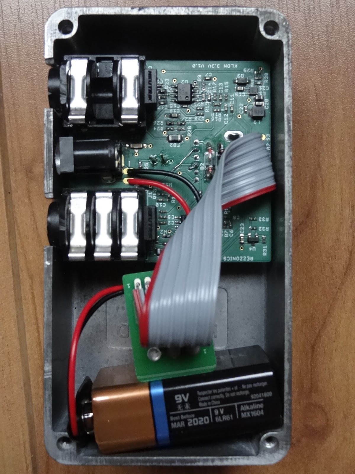
Once the circuit was fully assembled it seemed to fit well on the 1590B enclosure, but actually screwposts didn't allow the PCB border to touch the top enclosure sidewall so that DC jack would be receded probably avoiding proper DC plugging.
Components fitting on 1590B enclosure
The PCB was finally mounted with connectors on one enclosure side. Next time PCB corners will have to be chamfered and connectors placed closer to the center in order to mount it with connectors on top side of the enclosure.
Klone 3v3 clone fully assembled

Enclosure design and build

For the enclosure design I decided to use the etching technique. It was my second attempt and the results were not quite satisfactory.
Enclosure design was made using InkScape. A Star Wars trooper color image was converted to black and white, then inverted and mirrored, printed on a PNP blue paper with a laser printer and ironed on a previously sanded and polished enclosure. 


Enclosure design made using Inkscape
PNP transfer was a complete disaster so I finally used satin paper. Defaults were corrected with a permanent marker and etched
Enclosure view after PNP blue transfer (FAIL!!)
Etching was made using a mix of hydrogen peroxide and hydrochloric acid which I think it is actually too strong, I finally over-etched the design corroding more areas than I should. Permanent marker did not protected well the aluminium from acid attack. The final result was quite modest.
Klon 3v3 clone pedal finished
Plug it in and test!
Klon3v3 clone switched-on and ready for test

Electrical Test

For electrical test, a Velleman PCSGU250 oscilloscope and signal generator was used. Three different signals were used: a 300mVpp 440Hz sinewave, a 300mVpp 4kHz sinewave, and a 300mVpp 1kHz guitar string note sampled. Signal is injected in the guitar pedal input and signals are probed with oscilloscope in different parts of the circuit with different gain and treble settings (0-5-10): 
  • first buffer opamp output (out1a), 
  • second gain opamp output (out1b), 
  • clipping diodes output (clip), 
  • third opamp output (out2a) and 
  • fourth tone opamp output (out2b)
At 440Hz with gain set at maximum, the total gain of the circuit is >23, 17 and 10dB with treble set at 10, 5 and 0 respectively. Saturation happens with gain and treble set to 10 with an output signal that has 3.25Vpp.

At 4kHz with gain set at 10, the total gain of the circuit is 14, 1.8 and -7.7dB with treble set at 10, 5 and 0 respectively. At 4.4kHz and an input of 300mV, the maximum output level is 1.5Vpp.

With a 300mVpp 1kHz guitar string note signal the maximum level obtained is 2.6Vpp (15dB gain)
440Hz sinewave 300mVpp input
440Hw sinewave 1620mVpp gain amplifier output (gain=10, 15dB) (out1b)
440Hw sinewave 181mVpp gain amplifier output (gain=5, -4.2dB) (out1b)
440Hw sinewave 22mVpp gain amplifier output (gain=0, -23dB) (out1b)
440Hz sinewave 340mVpp clipped signal (gain=10, 1.2dB) (clip)
440Hz sinewave 260mVpp clipped signal (gain=0-5, -1.1dB) (clip)
440Hz sinewave 1490mVpp second opamp output (gain = 10, 14dB) (out2a)
440Hz sinewave 820mVpp second opamp output (gain = 5, 9dB) (out2a)
440Hz sinewave 540mVpp second opamp output (gain = 0, 5.2dB) (out2a)
440Hz sinewave 3250Vpp tone opamp (treble=10, gain=10, 22.6dB) (out2b)
440Hz sinewave 2130mVpp tone amp output (treble=5, gain=10, 17dB) (out2b)
440Hz sinewave 970mVpp tone amp output (treble=0, gain=10, 10dB) (out2b)
4.4kHz sinewave 2010mVpp gain amplifier output (gain=10, 16.6dB) (out1b)
4.4kHz sinewave 290mVpp gain amplifier output (gain=5, -0.23dB) (out1b)
4.4kHz sinewave 190mVpp gain amplifier output (gain=0, -3.73dB) (out1b)
4.4kHz sinewave 760mVpp clipped signal (gain=10, 8.4dB) (clip)
4.4kHz sinewave 280mVpp clipped signal (gain=5, -0.43dB) (clip)
4.4kHz sinewave 220mVpp clipped signal (gain=0, -2.53dB) (clip)
4.4kHz sinewave 280mVpp second opamp output (gain=10, -0.63dB) (out2a)
4.4kHz sinewave 112mVpp second opamp output (gain=5, -8.53dB) (out2a)
4.4kHz sinewave 60mVpp second opamp output (gain=0, -14dB) (out2a)
4.4kHz sinewave 1500mVpp tone amp output (treble=10, gain=10, 14dB) (out2b)
4.4kHz sinewave 370mVpp tone amp output (treble=5, gain=10, 1.8dB) (out2b)
4.4kHz sinewave 120mVpp tone amp output (treble=0, gain=10, -7.7dB) (out2b)
1kHz guitar note 280mVpp input
1kHz guitar note 39mVpp output (gain=0, treble=0, -18dB) (out2b)
1kHz guitar note 115mVpp output (gain=0, treble=5, -8.3dB) (out2b)
1kHz guitar note 480mVpp output (gain=0, treble=10, 2.4B) (out2b)
1kHz guitar note 76mVpp output (gain=5, treble=0, -11dB) (out2b)
1kHz guitar note 220mVpp output (gain=5, treble=5, -3.7dB) (out2b)
1kHz guitar note 970mVpp output (gain=5, treble=10, 8dB) (out2b)
1kHz guitar note 210mVpp output (gain=10, treble=0, -4.5dB) (out2b)
1kHz guitar note 710mVpp output (gain=10, treble=5, 4.6dB) (out2b)
1kHz guitar note 2590mVpp output (gain=10, treble=10, 15dB) (out2b)

Monday, 5 September 2016

Klon 3v3 Clone: Schematics and PCB layout

Klon 3v3 Clone Schematics

Klon 3v3 Clone schematics have been implemented using Eagle CAD. Op-amps used are TI LME49721, they are low-distortion, low-noise Rail-to-Rail Input/Output that can be powered between 2.2 and 5.5V. Passive values, resistors and capacitors have been changed to adapt to the power supply change from 9V to 3.3V, many of them have been multiplied by 3 and some of them adjusted to achieve a similar signal in all op-amp stages. Top gain potentiometer series resistor has been splitted into R4 and R5 on both sides of the potentiometer to avoid the low gain value obtained when this potentiometer is set to minimum. filter components around bottom gain potentiometer have been obtained by multiplying by 3 the original values.
Clipping diodes D1 and D2 are 1N34A germanium, they are not part of the BoM since they cannot be found through big distributors, specialized guitar pedal shops can stock them.
Gain resistors R7, R19, R23 have been tuned during simulations to obtain a similar saturation to original circuit on each stage, and then tweaked again on real circuit by ear. Note that values that appear in the BoM are those used on simulations and are lower than the final used values.
1nF capacitor C24 has been added for better circuit stability.

The 9V to 3.3V DC-DC converter is an integrated step-down controller TI TPS62122 in a tiny WSON-6 package. R29-R30 resistors set the FB reference voltage to get 3.3V on the output. A 22uH L1 inductor is required for the switching regulator. Switching frequency is as high as 800kHz, far from audible frequencies, but an additional LC filter, L2 100nH, C22 1uF has been added to reduce output ripple. recommended C19, C20 input output decoupling capacitors have been added to input and output respectively.

Mid 1.65V reference voltage for op-amps bias is generated by LM4041 reference voltage IC.

FB1-FB2 BLM31PG121SN1L are 120ohm ferrites to filter input and out signals respectively

9V input power supply is filtered using CF1 Murata NFM3DPC223R1H3L 22nF EMI filter.

D3 is an input power protection for inverted voltage.

The Klone 3v3 Clone BoM can be found on this link. Please review it before buying the components. Components used are SMD 0402 whenever possible.
Klon 3v3 Clone Eagle CAD Schematics

Klon 3v3 Clone PCB layout

Circuit has been implemented on a 54 x 54 mm 2-layer PCB that fits into a 1590B enclosure. 3.3V power supply is routed as a plan on top layer, and GND is routed as a plan on bottom layer.
Klone 3v3 Clone PCB layout: Top layer
Klone 3v3 Clone PCB layout: Bottom layer

Friday, 2 September 2016

Klon Centaur 3v3 Clone: LTspice analysis


Klon Centaur is one of the most famous, controversial, loved and talk-about guitar pedals and also one of the most cloned and copied ones, probably because it's quite expensive. Basically it's a Boost / Overdrive pedal with a gain, a treble and a volume control. It's subtly mixes the original signal with an amplified version of the signal that also goes through a germanium clipping section, before everything gets again amplified and filtered by the tone section that can considerably reinforce the mids.

Klon Centaur guitar boost/overdrive pedal
The first dual opamp section is powered between GND and 9V, but the second dual opamp section is powered between -9V and 18V to have more headroom before the opamps saturate. The circuit has a lot of gain and the signal that can get into the guitar power amp is huge, to breakout the guitar amp preamp section.

The main reason for making this project is to verify this idea I will expose here:

The output of most guitar pick-ups is usually several hundred millivolts peak-to-peak, 1Vpp is already a loud signal for a guitar amp. At the same time, guitar amps and specially valve amps are biased in a way that 2Vpp already saturates the input.Why then a guitar pedal should need more than 2Vpp or 3Vpp of headroom since those levels would be already enough to saturate the input and "breaking-up" the amp?

On the other hand, "breaking-up" or saturating the signal inside the pedal gives more control than "breaking-up" the guitar amp, because each model of guitar amp may have different input headroom and hence saturate earlier or later than others.

9V battery voltage is the "standard power" on guitar pedals, but that does not mean that the electronic circuits inside the pedal must be powered at 9V, they could be powered at a lower voltage and still have enough headroom for feeding the guitar amp.

Nowadays there exist very good audio opamps with very low harmonic distortion that can be powered at lower voltages and have rail-to-rail inputs and outputs.

If an efficient step-down converter is used, battery charge could be maximized and guitar pedal could have the same performance even at the end of the life of the battery. At a lower power we also could expect less power consumption and longer battery life. There exist cheap, efficient and stable step-down converters with a small footprint, they just need a small inductor, input and output capacitor and a couple of resistors to set the output voltage. Switching frequencies can be very high, so that any ripple in the power supply will not be audible, and additional LC filtering can be added to minimize ripple and noise.

With all that in mind I decided to do a Klon Centaur "3.3V clone" pedal.

Klon Centaur LTSpice analysis

I will start by doing a LTSpice simulation of the original circuit, and then I will try to implement a 3.3V circuit that tries to match the response of the original circuit.
Klon Centaur LTspice schematics

Klon Centaur Frequency response. Gain =0-10. Treble = 10
First we do a frequency response analysis between 10 Hz and 20kHz with treble set to 10 and varying gain from 0 to 10. Klon Centaur produces a high gain to small signal from 47dB @ 810Hz up to 75dB @ 674Hz reinforcing mids with peaks around 670 - 810Hz. Gains are much smaller at low and high frequencies.
Klon Centaur Frequency response. Gain =10. Treble = 0 - 10
Then we do a frequency response analysis between 10 Hz and 20kHz with gain set at 10 and treble varying from 0 to 10. Klon Centaur amplifies the signal at mids with a peak around 650Hz from 52 dB to 75 dB.
Klon Centaur Time response. Gain = 0-10. Treble = 10
Now we do a time response analysis during 25ms (only 6ms are shown) with gain between 0 to 10 and treble set to 10 using four 300mVpp sinewaves at different frequencies: 82Hz, 440Hz, 2kHz and 4kHz. The output obtained is a large amplitude signal more than 24Vpp that saturates the op-amps between -12 and 12V.
Klon Centaur Time response. Gain = 10. Treble = 0-10
Finally we do a time response analysis during 25ms (only 6ms are shown) with gain set to 10 and treble between 0 and 10 using the same four 300mVpp sinewaves. The output obtained only saturates the op-amps for high treble values.

Klone Centaur 3V3 clone LTSpice analysis

The Klone Centaur circuit is adapted to 3.3V using 3.3V rail-to-rail op-amps and passive values have been changed to provide a similar level of saturation, which means lower level of gain.
Klon Centaur 3V3 clone LTspice schematics
Klon 3V3 clone Frequency response. Gain =0-10. Treble = 10
Again we do a frequency response analysis between 10 Hz and 20kHz with treble set to 10 and varying gain from 0 to 10. Klon 3V3 clone produces a high gain to small signal from 20dB @ 1kHz up to 39dB @ 970Hz reinforcing mids with peaks around 970 - 1kHz. Gains are much smaller at low and high frequencies.
Klon 3V3 clone Frequency response. Gain =10. Treble = 0-10
Then we do a frequency response analysis between 10 Hz and 20kHz with gain set at 10 and treble varying from 0 to 10. Klon 3V3 clone amplifies the signal at mids with a peak around between 735 Hz to 970Hz from 21 dB to 39 dB.
Klon 3V3 clone time response. Gain = 0-10. Treble = 10
Now we do a time response analysis during 25ms (only 6ms are shown) with gain between 0 to 10 and treble set to 10 using four 300mVpp sinewaves at different frequencies: 82Hz, 440Hz, 2kHz and 4kHz. The output obtained is a large amplitude signal, but in this case op-amps saturate between -1.65 and 1.65V for a maximum signal of 3.3Vpp.
Klon 3V3 clone time response. Gain = 10. Treble = 0-10
Finally we do a time response analysis during 25ms (only 6ms are shown) with gain set to 10 and treble between 0 and 10 using the same four 300mVpp sinewaves. The output obtained only saturates the op-amps for high treble values but again maximum signal level is 3.3Vpp.

As we can see, frequency response gain has been reduced from a maximum of 75dB to 39dB, 36dB less in order to obtain a similar level of signal saturation in the time domain. The signal that will get to the guitar amp will be different in both pedals, specially at high gains, Klone Centaur pedal provides large signals of 24Vpp, while the 3v3 clone will provide 3.3Vpp signals at most. Will it sound very different? The only way to really know it is doing a real implementation of the effect.
Stay tuned for next post on effect practical implementation.