
______________________________
WARNING!!
This project implies the generation of very high voltages that may be harmful.
Please check your own safety when working with high voltages, use protective measures like rubber gloves and avoid proximity to high voltage areas of the circuit.
______________________________
WARNING!!
This project could generate ozone levels that could be dangerous for your health.
ASHRAE recommends that ozone levels should not exceed 0.05 ppm.
CSA recommends an ozone limit of 0.04ppm.
I have no means to measure the possible generation of ozone on this device.
Use it at your own risk.
ASHRAE recommends that ozone levels should not exceed 0.05 ppm.
CSA recommends an ozone limit of 0.04ppm.
I have no means to measure the possible generation of ozone on this device.
Use it at your own risk.
_______________________________

Many years ago I discovered an article on an electronic magazine on a simple negative ion generator, based on cascaded capacitor-diode voltage multiplier from a regular 220VAC mains supply. The article described the benefits of negative ions as air purifier, removing dust, pollen and other contaminants from air, the presence of negative ions on water falls and other idylic places where you find calm and relaxation, how the air is charged with positive ions before a storm creating an oppressive and heavy atmosphere and how the air is charged with negative ions after the storm. So I decided to make this simple negative ion generator with a single big needle that concentrated a high negative voltage on its tip.
I found on another electronic magazine another negative ion generator boxed kit that had several needles. The circuit was a bit more complex, using an oscillator at higher frequency and a high voltage transformer plus the capacitor-diode voltage multipliers at the end. It worked OK but the dust and smoke deposited on the plastic box and around it leaving a dark stain around the ion generator, the transformer also generated a high pitch noise almost inaudible but that could be annoying at a work place.
The tips of the needles glowed and there was this peculiar ozone smell, which I found quite pleasant that reminded this smell after a storm. By reading through internet I found that a too high negative voltage (corona effect) can actually ionize the oxygen in the air and create ozone, which actually can be harmful if one is exposed to certain levels for a long time.
Years later I decided to make my own negative ion generator design but adding several features:
- A quiet fan with variable speed to move dirty air through the ion generator
- A disposable carbon filter where the dirt could be retained
- A variable ionizing high voltage
- Avoid the use of noisy and bulky transformers
A step-up switching regulator actually chops a DC voltage generating a square wave that can then be filtered to a DC voltage with a capacitor-diode filter. If the regulator is adjustable by adding a potentiometer in the feedback input of the regulator, the converter generates a square signal that once filtered could generate and adjustable DC voltage output, then reusing the same square voltage output of the regulator and adding a capacitor-voltage multiplier a high negative voltage output could be also generated.
The first step was to find a step-up DC-DC regulator with the highest input voltage possible. Initially I thought that I should use an inverting regulator where the output voltage should be negative, since the voltage multiplier had to generate a negative high voltage, but actually I could connect a simple capacitor-diode to generate a positive regulated output voltage to be used by the feedback resistor bridge and in parallel connect the capacitor-diode voltage multiplier to generate the high negative voltage.
I found a Linear Technology step-up regulator, LT3758A that could fit my needs. This device supports an input voltage of up to 100V, there are not many DC-DC regulators that actually support this high input voltage. This device can be used in isolated flyback, SEPIC, inverting (my first idea) and boost (step-up) configuration. I used it in boost configuration.
The next step was to generate a DC high input voltage from the mains 220VAC supply, the usual method would be to use a transformer, but I wanted to get rid of the transformer. Usually a negative ion generator does not need very high currents since the goal is to generate a very high negative voltage that generates negative ions in the air, so the current required is mostly the current generated by the switching regulator plus the leaked current through the air and capacitor slow discharge.
An easy transformerless AC-DC power supply uses a resistor-capacitor impedance followed by a diode bridge and a zener diode to set up the output voltage. In order to be in the secure zone of the voltage regulator I decided to use 75VDC output at 120mA output current for a total of less than 10W power consumption.
Finally I selected a quiet 220VAC fan, the ORION OA92-22-2TB, and a speed regulator circuit based on a triac and a diac.
LTSpice simulations:
The figure below shows negative ion main circuit simulations schematics consisting of 75V to 350V step-up regulator and capacitor-diode voltage multiplier with 20 stages.
The figure below shows the waveforms of the switching signal at the output of the MOSFET and inductor (Vi1), and the "regulated" output voltage (Vo1) with the output voltage control potentiometer at minimum, 120 kohm on the top resistor and 1 kohm on the bottom resistor for a Vfb=1.6V, which corresponds to Vo1 = 194V. The output voltage is approximately 200V, it shows a lot of ripple because the capacitor used for the diode-capacitor filter is quite low, 4.7nF, but the goal is to keep the regulator switching to actually charge the voltage multiplier.

The figure below shows the output of the 20 capacitor-diode stages voltage multiplier (Vout) which is approximately -1.8kV, which corresponds to a voltage multiplication factor of more than 9 times.

The figure below shows the waveforms of the switching signal at the output of the MOSFET and inductor (Vi1), and the "regulated" output voltage (Vo1) with the output voltage control potentiometer at maximum, 220 kohm on the top resistor and 1 kohm on the bottom resistor for a Vfb = 1.6V, which corresponds to Vo1 = 353V. The output voltage is approximately 350V.

The figure below shows the output of the 20 capacitor-diode stages voltage multiplier (Vout) which is approximately -3.3kV !!

Below are the schematics of the 220VAC to 75VDC transformerless converter based on 2.2uF capacitor, bridge diode, 75V Zener diode and 75V TVS diode. The TVS diode has been added for extra overvoltage protection. The circuit is calculated for a current consumption of less than 150mA.

The figure below shows the output voltage of the transformerless AC-DC regulator, for an initial current of 120mA, followed by a zero current load, the output voltage goes from 75V @ 120mA to 84V @ 0mA:

This circuit actually has an issue because it has an almost constant power consumption of 75Vx120mA= 9W, if there is no load, most of the power consumption goes to the Zener and TVS diodes which actually could get hot and even exceed maximum power dissipation. The following figure shows the power consumption on the load, the 75V Zener diode and the 75V TVS diode at 120mA and at 0 mA:
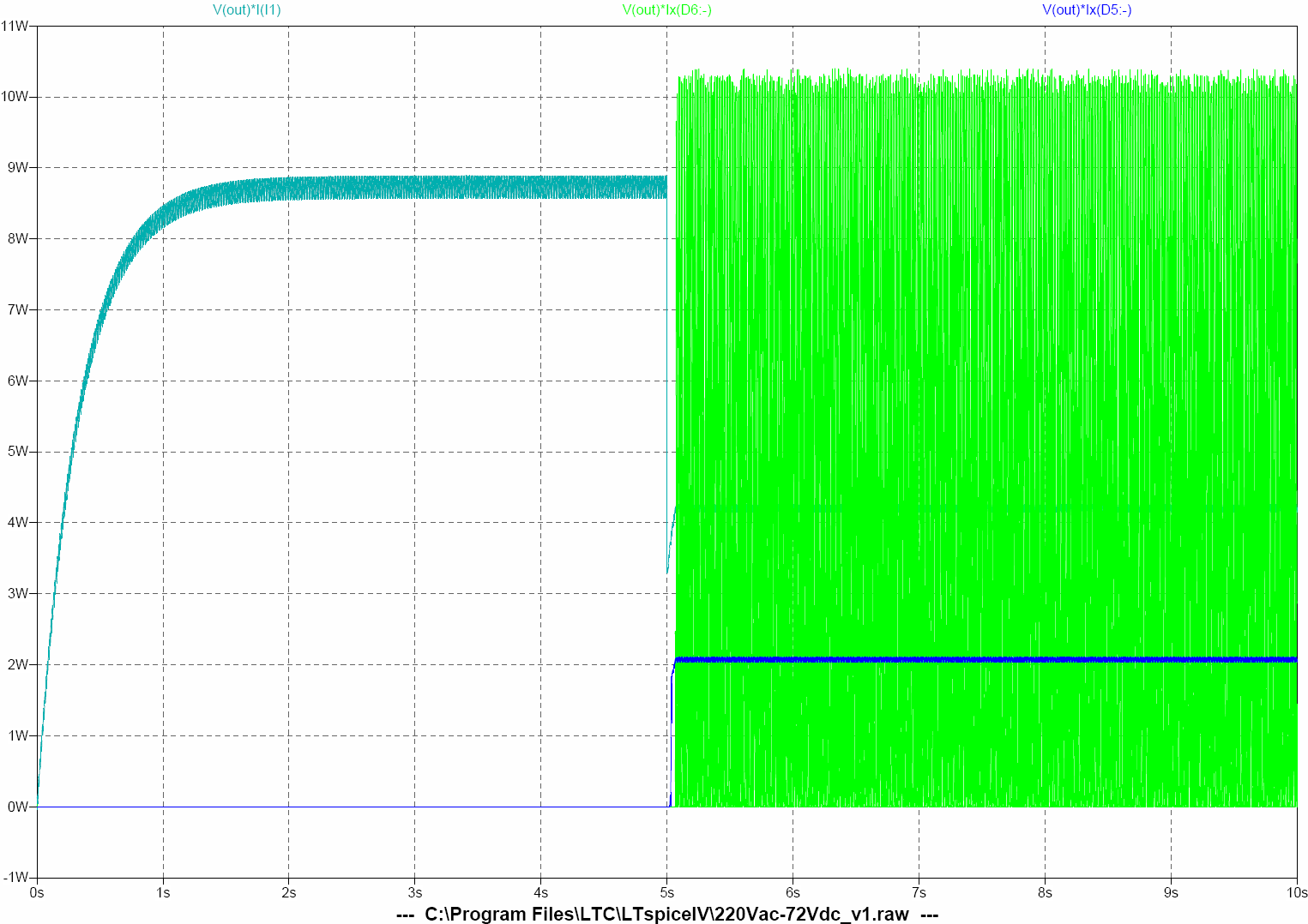
When the load is at maximum 120mA most of the power, 8.7W, is dissipated by the load, but at a low load of 50mA only 4W are dissipated by the load and the rest of the power goes to the 75V Zener diode, 2W, and almost 4W to the 75V TVS diode, peak power of 10W but RMS power of 5W.
The problem of this circuit is that the load is quite variable, the 75V to 350V step-up DC-DC converter demands a peak of current at start-up but once the output capacitors are charged there is almost no current consumption apart from the switching to keep the capacitors charged. Zener diode has to be calculated for 3W or more and TVS diode for 5W or more to have some margin and they still will get hot.
Actually once the circuit was finished, the peak current at start-up was excessive and the output of the AC-DC never got to 75V, the 2.2uF capacitor (C3 in the simulation schematics) had to be increased adding a 0.68uF capacitor (C4). This value was manually adjusted by progressively increasing the capacity from 0.1uF until the AC-DC output reached 75V, but then, when the load was low, Zener and TVS diodes exceeded their rated power.
The 75V Zener diode had to be changed from an SMA 3W to an SMC 5W, and the 75V TVS diode had to be changed from SMA 3.3W to SMC 6.5W.
_________________
Controversy around the safety of negative ion generators, air purifiers, ozone generators:
In a negative ion generator, the positive side of a high voltage source is grounded, where the negative side is attached to a sharply pronged antenna. The antenna allows the negative voltage to "stream out", creating negative ions.
ReplyDeletePower transformers in India | Transformer manufacturer in India
I like this topic. I want know some helpful things from this side.
ReplyDeletegenerator hire & diesel generator hire