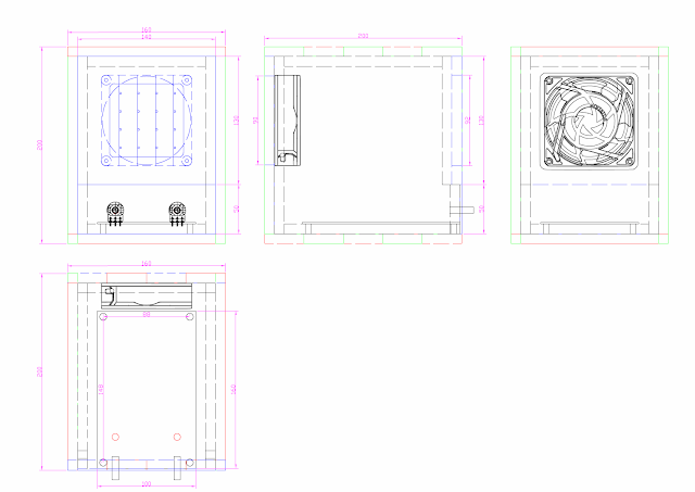
Find here below mechanical drawings with dimensions. Front and rear sides are shown in blue. Top and bottom sides in red and left and right sides in green.
The box consists of a basic frame where left-right sides and top-bottom sides where joined using finger joints 40 mm long 10 mm deep. 3x40 mm fingers on each panel side are joined to 2x40 mm fingers on the adjacent panel. Wood paste was used to cover the
There is a squared chamfered 75 mm window in the front cover (140 x 130 mm), where the ionizer needle grid will be installed. An aluminum panel 140 x 50 mm and 2 mm thick is used to install 2 potentiometers, one switch and one blue LED.
The rear cover (180 x 140 mm) has a circular hole Ø90 mm for the fan air exhaust. All sides and corners are filed and rounded to allow covering with red tolex.
10 mm square wood cleats made out of the same plywood are used to reinforce the corners. they are glued leaving 10 mm distance to the front and rear borders to allow installing the front and rear covers. Only 2 mm are left for the aluminum plate on the front bottom side as shown in the picture below.
The box front panel as well as the inside has been painted in red. A red tolex has been glued on the top, bottom, left and right sides.
The PCB fully assembled with front panel, potentiometers, knobs, power-on switch and power-on blue LED. PCB has been connected with wire cables to the AC outlet, fan and ionizer needle grid ready for testing with a digital multimeter.
The rear panel has been covered with tolex too. The picture below shows the fan installed with a plastic fanguard with filter. A wire frame has been installed in order to place an additional disposable carbon filter.The AC outlet includes a fuse.The needle grid is made out of 1 mm thick wire and nails. Four segments of wire where soldered to a square frame of wire. Four nails where soldered to each wire segment for a 16 pins needle grid.
The picture below shows the front panel with the needle grid installed as well as the aluminum faceplate with two knobs, power-on swith and power-on blue LED. The left button controls the output voltage of the ionizer, and the right button controls the speed of the fan. There is no risk in touching the needle grid or the screws connected to high voltage because they are protected with high impedance resistors, but an additional plastic cover could be added.


No comments:
Post a Comment