Google statistics

Friday, 8 May 2015

Transformerless Negative Ion Generator - Simulations (1/3)

______________________________
WARNING!! 
This project implies the generation of very high voltages that may be harmful. 
Please check your own safety when working with high voltages, use protective measures like rubber gloves and avoid proximity to high voltage areas of the circuit.
______________________________
WARNING!! 
This project could generate ozone levels that could be dangerous for your health.
ASHRAE recommends that ozone levels should not exceed 0.05 ppm.
CSA recommends an ozone limit of 0.04ppm.
I have no means to measure the possible generation of ozone on this device.
Use it at your own risk.
_______________________________

There is actually a lot of controversy going around regarding the dangers, safety and healthy properties of air purifiers, negative ion or ozone generators, specially regarding some cheap models found on the internet. I don't want to hide these discussions and I invite you to inform you on this matter before you decide to go on and build a negative ion generator. Use it at your own risk. I will post some videos at the end of this post.

Many years ago I discovered an article on an electronic magazine on a simple negative ion generator, based on cascaded capacitor-diode voltage multiplier from a regular 220VAC mains supply. The article described the benefits of negative ions as air purifier, removing dust, pollen and other contaminants from air, the presence of negative ions on water falls and other idylic places where you find calm and relaxation, how the air is charged with positive ions before a storm creating an oppressive and heavy atmosphere and how the air is charged with negative ions after the storm. So I decided to make this simple negative ion generator with a single big needle that concentrated a high negative voltage on its tip.

In order to test it I filled a glass jar with smoke and I put the needle inside the inverted jar so that the smoke could not slip out. When the generator was switched on a turbulence was created within the container and after a couple of minutes there was no trace of smoke inside the jar. I showed the smoke test to my father and he was so impressed that asked me to make an ion generator to put on his office, at the time it was allowed to smoke in the work places.

I found on another electronic magazine another negative ion generator boxed kit that had several needles. The circuit was a bit more complex, using an oscillator at higher frequency and a high voltage transformer plus the capacitor-diode voltage multipliers at the end. It worked OK but the dust and smoke deposited on the plastic box and around it leaving a dark stain around the ion generator, the transformer also generated a high pitch noise almost inaudible but that could be annoying at a work place.

The tips of the needles glowed and there was this peculiar ozone smell, which I found quite pleasant that reminded this smell after a storm. By reading through internet I found that a too high negative voltage (corona effect) can actually ionize the oxygen in the air and create ozone, which actually can be harmful if one is exposed to certain levels for a long time.

Years later I decided to make my own negative ion generator design but adding several features:
  • A quiet fan with variable speed to move dirty air through the ion generator
  • A disposable carbon filter where the dirt could be retained
  • A variable ionizing high voltage
  • Avoid the use of noisy and bulky transformers
I thought of using a high voltage (around 220Vrms) oscillator at a higher frequency than the mains 50/60Hz so that could be easily filtered with low capacitor values, for example 1MHz.

A step-up switching regulator actually chops a DC voltage generating a square wave that can then be filtered to a DC voltage with a capacitor-diode filter. If the regulator is adjustable by adding a potentiometer in the feedback input of the regulator, the converter generates a square signal that once filtered could generate and adjustable DC voltage output, then reusing the same square voltage output of the regulator and adding a capacitor-voltage multiplier a high negative voltage output could be also generated.

The first step was to find a step-up DC-DC regulator with the highest input voltage possible. Initially I thought that I should use an inverting regulator where the output voltage should be negative, since the voltage multiplier had to generate a negative high voltage, but actually I could connect a simple capacitor-diode to generate a positive regulated output voltage to be used by the feedback resistor bridge and in parallel connect the capacitor-diode voltage multiplier to generate the high negative voltage.

I found a Linear Technology step-up regulator, LT3758A that could fit my needs. This device supports an input voltage of up to 100V, there are not many DC-DC regulators that actually support this high input voltage.  This device can be used in isolated flyback, SEPIC, inverting (my first idea) and boost (step-up) configuration. I used it in boost configuration.

The next step was to generate a DC high input voltage from the mains 220VAC supply, the usual method would be to use a transformer, but I wanted to get rid of the transformer. Usually a negative ion generator does not need very high currents since the goal is to generate a very high negative voltage that generates negative ions in the air, so the current required is mostly the current generated by the switching regulator plus the leaked current through the air and capacitor slow discharge.

An easy transformerless AC-DC power supply uses a resistor-capacitor impedance followed by a diode bridge and a zener diode to set up the output voltage. In order to be in the secure zone of the voltage regulator I decided to use 75VDC output at 120mA output current for a total of less than 10W power consumption.

Finally I selected a quiet 220VAC fan, the ORION OA92-22-2TB, and a speed regulator circuit based on a triac and a diac.

LTSpice simulations:

The figure below shows negative ion main circuit simulations schematics consisting of 75V to 350V step-up regulator and capacitor-diode voltage multiplier with 20 stages.

The figure below shows the waveforms of the switching signal at the output of the MOSFET and inductor (Vi1), and the "regulated" output voltage (Vo1) with the output voltage control potentiometer at minimum, 120 kohm on the top resistor and 1 kohm on the bottom resistor for a Vfb=1.6V, which corresponds to Vo1 = 194V. The output voltage is approximately 200V, it shows a lot of ripple because the capacitor used for the diode-capacitor filter is quite low, 4.7nF, but the goal is to keep the regulator switching to actually charge the voltage multiplier.
The figure below shows the output of the 20 capacitor-diode stages voltage multiplier (Vout) which is approximately -1.8kV, which corresponds to a voltage multiplication factor of more than 9 times.
The figure below shows the waveforms of the switching signal at the output of the MOSFET and inductor (Vi1), and the "regulated" output voltage (Vo1) with the output voltage control potentiometer at maximum, 220 kohm on the top resistor and 1 kohm on the bottom resistor for a Vfb = 1.6V, which corresponds to Vo1 = 353V. The output voltage is approximately 350V.

The figure below shows the output of the 20 capacitor-diode stages voltage multiplier (Vout) which is approximately -3.3kV !!
Below are the schematics of the 220VAC to 75VDC transformerless converter based on 2.2uF capacitor, bridge diode, 75V Zener diode and 75V TVS diode. The TVS diode has been added for extra overvoltage protection. The circuit is calculated for a current consumption of less than 150mA.
The figure below shows the output voltage of the transformerless AC-DC regulator, for an initial current of 120mA, followed by a zero current load, the output voltage goes from 75V @ 120mA to 84V @ 0mA:
This circuit actually has an issue because it has an almost constant power consumption of 75Vx120mA= 9W, if there is no load, most of the power consumption goes to the Zener and TVS diodes which actually could get hot and even exceed maximum power dissipation. The following figure shows the power consumption on the load, the 75V Zener diode and the 75V TVS diode at 120mA and at 0 mA:
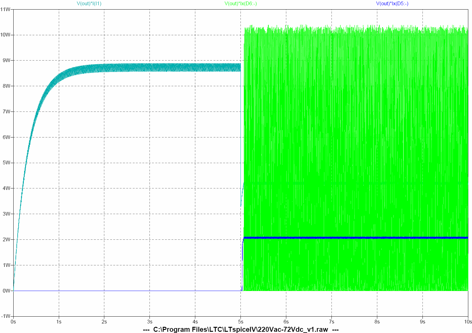
When the load is at maximum 120mA most of the power, 8.7W, is dissipated by the load, but at a low load of 50mA only 4W are dissipated by the load and the rest of the power goes to the 75V Zener diode, 2W, and almost 4W to the 75V TVS diode, peak power of 10W but RMS power of 5W.

The problem of this circuit is that the load is quite variable, the 75V to 350V step-up DC-DC converter demands a peak of current at start-up but once the output capacitors are charged there is almost no current consumption apart from the switching to keep the capacitors charged. Zener diode has to be calculated for 3W or more and TVS diode for 5W or more to have some margin and they still will get hot.

Actually once the circuit was finished, the peak current at start-up was excessive and the output of the AC-DC never got to 75V, the 2.2uF capacitor (C3 in the simulation schematics) had to be increased adding a 0.68uF capacitor (C4). This value was manually adjusted by progressively increasing the capacity from 0.1uF until the AC-DC output reached 75V, but then, when the load was low, Zener and TVS diodes exceeded their rated power.

The 75V Zener diode had to be changed from an SMA 3W to an SMC 5W, and the 75V TVS diode had to be changed from SMA 3.3W to SMC 6.5W.
_________________
Controversy around the safety of negative ion generators, air purifiers, ozone generators:

Saturday, 29 November 2014

Shin-Ei Fuzz-Wah - Univox/Unicord Super Fuzz - Sound check (4/4)

The reference signal is just a sequence of chords recorded into the computer with the pedal in bypass mode. This is the bypassed clean signal: This is the same sequence of chords with Fuzz at maximum gain, tone cut off and Wah off: It's a rough tone with lots of high harmonics due to the octaver fuzz without tone filtering. Now the chord sequence with Fuzz maximum gain but this time the tone cut filter is on. Wah is off. High harmonics are somewhat reduced while mid tones are reinforced by the tone cut filter. Chord sequence with Fuzz at maximum gain, tone cut is off, Wah is on: This time a guitar riff is used instead of a sequence of chords, Fuzz is set at maximum gain, Wah is of, tone cut filter is set consecutively off and on: Guitar riff with fuzz at maximum gain, Wah is on, tone cut filter is set alternatively on and then off: This is the playlist with all the different sounds used in the sound check for comparison: I thought that the best way to check the sound of the Super Fuzz-Wah pedal was on a real song, so this is the cover of Jesus & Mary Chain's song Just Like Honey, from their album Psychocandy. The Fuzz-Wah pedal was connected as input to the TubeSim amp and Rezzonics 1x12 cabinet speaker:

Source files

If you want to build you own SuperFuzzWah pedal find Eagle 6.3.0 files (Schematics, PCB, gerbers, BoM) on this github repository

Shin-Ei Fuzz-Wah - Univox/Unicord Super Fuzz - Pedal assembly (3/4)

The Fuzz-Wah was mounted on a 1590B Hammond enclosure, with two NKK M2012SS1W01 SPDT ON-ON switches, two Alpha RV16AF-10-20R1-A100K 16 mm A100K potentiometers, one Alpha RV16AF-10-20R1-A50K 16 mm A50K potentiometer, one Neutrik NMJ6HCD2 1/4'' Stereo phone jack as input connector, one Neutrik NMJ4HCD2 1/4'' Mono phone jack as output connector, one Alpha SF17020F-0302-21R-L 3PDT foot pushbutton switch, one Switchcraft 722A 2 mm DC power jack, one 5 mm blue LED, one 5mm LED bezel chrome, one 9V battery snap, and three black flute knobs with line indicator.

I buy most of the electronics at Mouser website, but some of the accessories are difficult to find, so there is an excellent German website specialized in pedals kits, components and accessories called Musikding.

It's quite hard to pack PCB, pots, jacks, battery and switches on a 1590B enclosure, so in order to design, plan and place all the different components I create a three view drawing with all the components on Inkscape. Inkscape allows copying an image from a pdf datasheet  convert it into a vectorial drawing,with the powerful Trace Bitmap tool, edit and delete lines or points, scale it and group all the lines into a single component that then can be moved and properly placed. This allows getting a better idea on how everything is going to fit in and avoid having troubles and discovering too late that a component does not properly fit. See the picture below. This is extremely useful, specially in this case, where it's extremely challenging to place three knobs and pots, two toggle switches and one foot push button switch on the faceplate. We have to be sure that everything fits in a there is enough place to add the faceplate design:
Fig 1. Inkscape three view pedal mechanical drawing
I also use Inkscape to design the faceplate. I create numbered knob dials, symbols, shapes, texts and drills as a group of lines that I can later reuse. In this case I used Aeroplane Flies High font for the Rezzonics and Rezz Fuzz v2 labels:

I did a simple design in blue and printed it on a transparent sheet. I decided rather not paint the enclosure but sand and polish the aluminum to leave it's natural metallic color and glue the transparent sheet with the faceplate design in blue. In order to better protect the laser printer blue ink, I printed the design in reverse, Inkscape allows easily reversing or flipping the design.

Water sanding to finer grains and polishing is quite a tedious work but the final chrome-like result is quite nice. Afterwards, holes are made using a multi-drill bit, I recommend using this type of drill for better results.

I used a repositionable adhesive spray to glue the transparent sheet. Faceplate shape is cut and adjusted to the enclosure after water sanding and polishing. Adhesive is applied to the transparent sheet and leave for 2 minutes to let evaporate and reduce the number of bubbles, then is firmly applied using a clean cloth with outwards movements, avoiding formation of bubbles and taking care that the faceplace keeps aligned with the borders and does not slides out of the enclosure faceplate.
The little defects, shades, and bubbles, disappeared as the adhesive dried out.
The Fuzz-Wah pedal finished. Knobs are Main volume or Level, Fuzz Gain, Wah frequency, Wah off-on switch and tone cut off-on switch. Footswitch is a true bypass.

The pedal finished and powered-on.

Monday, 24 November 2014

Shin-Ei Fuzz-Wah - Univox/Unicord Super Fuzz - debug and verification (2/4)

The Fuzz-Wah pedal must first be powered with an external +9V DC power supply (AC/DC adapter or 9V battery). If an external AC/DC adapter is used tip is connected to - and sleeve to +.
See this blog entry for additional information on debugging instruments used (multimeter, signal generator and oscilloscope)
The first stage is the verification of DC voltages with a multimeter, +9V DC input is doubled by U1 charge pump regulator ICL7660S. The voltage at the output of the dual diode D2 is actually closer to +16V due to the diodes drop.
We will compare the results of the real pedal with the LTSpice simulation.
Fuzz-Wah pedal schematics
LTSpice Schematics
The next step is to use a signal generator and check the signals on the different test points with an oscilloscope. I used a 2.5 kHz 0.3V peak-to-peak sinewave at the input. See figure 1.
Fig 1. 2.5 kHz 0.3 V peak-to-peak sinewave at the input (TP1)
Q1 and Q2 amplify the input signal and define the maximum gain of the signal. Gain potentiometer R9 allows reducing the level of the amplified signal.

The signal at TP2 after a two transistors (Q1, Q2) amplifier is amplified by 15.4 with a voltage amplitude of 4.63V peak-to-peak
Fig 2. 2.5 kHz 4.63 V peak-to-peak sinewave after Q1-Q2 amplifier (TP2)
Fig 2.1. LTSpice simulation at TP2
Q3 is a transistor amplifier. Signals at the collector and emitter are used as input  to the octave doubler Q4, Q5. Gain potentiometer R9 is set to maximum. The signal at TP3 at the base of Q5 and connected to the emitter of Q3 through a resistor in series with a capacitor has an amplitude of 4.19 Vpp and appears slightly clipped on the positive cycles.
Fig 3. 2.5 kHz 4.19 Vpp clipped sinewave after Q3 emitter at Q5 base (TP3)
Fig 3.1. LTSpice simulation at TP3
The signal at TP4 at the base of Q4 and connected to the collector of Q3 through a resistor in series with a capacitor has an amplitude of 5.66 Vpp and appears clipped on the positive cycle and sharped on the negative cycle.
Fig 4. 2.5 kHz 5.66 Vpp clipped and distorted sinewave after Q3 collector and Q4 base (TP4)
Fig 4.1. LTSpice simulation at TP4
Q4 and Q5 implement the octave doubler, the signal at TP5 at Q4-Q5 collectors has a frequency of 5 kHz, double of the input signal, with an amplitude of 0.77 Vpp. Both cycles are strongly clipped.
Fig 5. 5kHz 0.77 Vpp frequency doubled and clipped signal at Q4-Q5 collector (TP5)
Fig 5.1. LTSPice simulation at TP5
Dual Schottky diode D1 in series with R22 (100 ohms) clips the signal in a similar fashion to a germanium diode (see this blog entry for additional information on the use of Schottky diodes to replace germanium diodes). Signal on TP9 is very similar to the signal at TP5, since between them there is only a 10uF AC coupling capacitor to remove DC biasing.
Fig 6. 5kHz 0.78 Vpp frequency doubled and clipped signal at R22 + D1 clipping diode (TP9)
Fig 6.1. LTSpice simulation at TP9
R25, R26, C12, C13 implement the tone cut filter, R23, R24 implement a voltage divider so that the signal level at TP10 is similar when cut tone is used or bypassed by S2 switch.
Signal at TP6 is TP9 clipped and frequency doubled signal after the tone cut filter. It has an amplitude of 0.61 Vpp.
Fig 7. Signal after Tone cut filter 0.61Vpp (TP6)
Fig 7.1. LTSpice simulation at TP6
Signal at TP8 is TP9 clipped and frequency doubled signal after voltage divider and has an amplitude of 124 mVpp. R27 is the main volume potentiometer and is set to maximum.
Fig 8. Signal after voltage divider 0.124 Vpp (TP8)
Fig 8.1 LTSPice simulation at TP8
Q6 is another transistor amplifier which is the output of the fuzz effect without wah. Fuzz signal at TP12 when tone cut filter is bypassed has an amplitude of 0.53 Vpp
Fig 9. Signal at the output of Fuzz effect with Tone Cut filter bypassed (TP12)
Fig 9.1. LTSpice simulation at TP12
Signal at the output of the fuzz effect (TP12 ) when tone cut filter is on has an amplitude of 1.28 Vpp.
Fig 10. Signal at the output of Fuzz effect with Tone Cut filter on (TP12)
Fig 10.1 LTSpice simulation at TP12
Q7, Q8, Q9 transistors implement the Wah effect. R43 is the Wah potentiometer that tunes the Wah band-pass filter frequency.
Signal at Q7 collector (TP13) with Tone cut filter off and wah at potentiometer at 0 has an amplitude of 2 Vpp.
Fig 11. Signal at Q7 collector with Tone cut filter off and Wah pot at 0 (TP13)
Fig 11.1. LTSpice simulation at TP13
Signal at Q7 collector (TP13) with Tone cut filter off and wah at potentiometer at 10 has an amplitude of 99 mVpp. 
Fig 12. Signal at Q7 collector with Tone cut filter off and Wah pot at 10 (TP13)
Fig 12.1. LTSpice simulation at TP13
Signal at the output of Wah effect (TP15) with Tone cut filter on and wah pot at 0 has an amplitude of 2.9 Vpp.
Fig 13. Signal at Wah output with Tone cut filter on and Wah pot at 0 (TP15)
Fig 13.1 LTSpice simulation at TP15

Thursday, 20 November 2014

Shin-Ei Fuzz-Wah - Univox/Unicord Super Fuzz (not a clone!) - Schematics, PCB layout, simulations (1/4)

(Update 23/08/2015: Source files on Github)
I am a big fan of shoegaze / noise rock bands and one of my favourites bands is Jesus & Mary Chain and their album Psychocandy. That album is well known for its unique and characteristic dense wall of sound with that white noise (switch-on vacuum cleaner, washing machine and all appliances and let them couple to the guitar amp) that served as inspiration for a coming shoegaze generation of bands: Ride, My Bloody Valentine, Cocteau Twins, Lush, Spacemen 3, Loop... and even today shoegaze bands like A Place To Bury Strangers, Skywave, Ceremony, Screen Vinyl Image or 93MillionMilesFromTheSun, The KVB, The Lost Rivers, The Soft Moon...
It seems that one of the keys of that sound is the use of a Shin Ei Fuzz-Wah (8 transistors) pedal. This is a two/three effects into one pedal, a 6 transistor fuzz with octaver (high octave) plus a 2 transistor Wah effect at the end. JAMC did not make lots of use of the Wah pedal as it is normally used, but they used it to reinforce the gain of a band in the mid tones to couple the sound, so they set the pedal at one position and didn't move it.
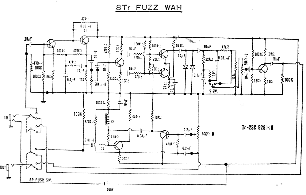
These are the schematics of the original Shin Ei Fuzz-Wah pedal:

The fuzz with octaver is also used on the Univox/Unicord Super Fuzz (6 transistors) pedal. See schematics here:
Find here a demo video of the Shin Ei Fuzz-Wah pedal:
With all that in mind I made a first version of the Super Fuzz with Octaver pedal with scrapped through-hole conventional components on a Vero board using 2N2219A transistors 
 The first version on the Super Fuzz pedal can be seen here on the left of the picture:
The result was quite deceiving, the circuit has lots of gain and it was too noisy, too much, even for playing a PsychoCandy cover, specially when powered at 9V. A higher DC power of 15V reduced a bit the noise but it was still an undesirable result.

Schematics

(Update 23/08/2015: Source files on Github)
I decided to restart the work using surface mount devices (SMD), a professional PCB and include the Wah sections as well as several improvements and modifications to the original circuit.
These are the schematics of the Super Fuzz-Wah design:

I used BC847C high gain (hfe = 520typ) SMD SOT-23 NPN transistors.
The improvements on the circuit are the following:
  1. Replacing the two clipping germanium diodes by one dual BAT54S Schottky diode SOT-23 in series with 100 ohms (D1, R22).
  2. Replacing the Wah bulky and expensive inductor by a gyrator circuit based on a transistor (Q9) plus capacitor and biasing resistors.
  3. Doubling the 9V DC power supply, with a charge pump circuit based on Intersil ICL7660SCBA
Check my post on replacing germanium diodes with Schottky diodes plus series resistor.

The charge pump regulator ICL7660SCBA allows doubling the power supply from 9V to 18V, however this charge pump regulator uses an internal oscillator with a quite low and audible switching frequency of 10 kHz. If it is used in its default oscillation mode this frequency is seen as a ripple frequency on the power supply, since this pedal has lots of gain in its transistor circuits, this ripple noise can be amplified and heard as a very nasty and unpleasant high pitch noise. For that reason, it is absolutely required to short pin 1 (boost frequency pin) with pin 8 (V+) in order to get a higher switching frequency of 35 kHz, out of the audible spectrum.

Wah circuit simulation with LTSpice

(Update 23/08/2015: Source files on Github)
The following schematics shows both Wah circuits: to the right the original wah circuit based on an inductor, and to the left the circuit based on a gyrator circuit, where the inductor has been replaced by a transistor plus capacitor and biasing resistors. Basically the circuit framed by the square on the right side is replaced by the circuit framed by the square on the left.
This is the frequency response of the original circuit when varying the wah potentiometer:
It is a tuned band-pass filter with its peak moving from 240 Hz to 1.28 kHz, increasing the gain from 12.5 to 23.5 dB.
And this is the frequency response of the gyrator circuit when varying the potentiometer:
Again it is a tuned band-pass filter with its peak moving from 260Hz to 1.28 kHz, slightly increasing the gain from 16.5 dB to 19.2dB.
So we obtain a quite similar result with even a more stable gain peak.

PCB Layout

(Update 23/08/2015: Source files on Github)
The PCB was made on two layers with dimensions of 80 mm x 50 mm:

Schematics and PCB layout was designed using Eagle CAD. The PCB layout can be uploaded into Eurocircuits website, and a quote can be obtained immediately, I paid 70 € for 2 boards prototypes in a 7 day turnaround, the quality is really good.
I purchased the components at Mouser website. You can find here the BoM, total cost of components for one prototype was 26 €.
To solder the components I used a low temperature (138°C ) CR11 solder paste Sn42Bi58 and a hot air soldering station, the results are very professional and clean. This is the finished PCB with all components (except external switches, jacks and potentiometers) mounted.
All the cables, jacks, connectors, switches and potentiometers soldered and ready for debug and verification

Sunday, 16 November 2014

Tube Simulator - Sound check and AC30 emulators comparative

I wanted to do a sound check of the TubeSim v1.0 VOX AC30 valve amplifier emulator and a comparative with other VOX AC30 amp emulators. This is it.

First I found on the web a sound file with a clean guitar riff: Then I fed this sound file from the computer Line output into the TubeSim Line input. The TubeSim 25W 8 Ω output was connected into the Rezzonics v12 DIY Cabinet speaker with a Celestion Vintage 30 12''. The output sound was recorded with Audacity in the computer using an AKG D40S dynamic condenser microphone (it's a vocal microphone but that's the best I could get for the sound check)

This is the TubeSim v1.0 guitar riff sound with gain at maximum, no bass, no treble, tone cut off:

I think the sound has a nice crispy distortion, with lots of mids and lots of sustain.

The best would have been to compare it with a real VOX AC30 valve amplifier, but unfortunately I don't own one.
I decided to compare with several amp emulators.
First the open source amp emulator Poulin HyBrit Head v1.1 in the same conditions, maximum gain, no equalization:

The Poulin HyBrit Head v1.1 has a lot of gain too, it's more saturated quite brittle with more treble than the TubeSim v1.0

Now the GuitarRig 2 ACBox GuitarRig 2 ACBox resembles more the TubeSim, less saturated than the Poulin with maybe more bass than the TubeSim v1.0

Amplitube 3 offers two different AC30-like amp emulators: Amplitube 3 Hot AC30: The Amplitube 3 Hot AC30 is less crispy, lots of bass, not much saturation, it's a bit muddy and more somber, less sustain. In my opinion is the worst sounding of all the amp emulators.

Amplitube 3 Hot AC30 Copper:
Amplitube 2 Hot AC30 Copper is a bit more saturated than the previous one, not much sustain, less muddy, more mids, similar to the Guitar Rig 2 ACBox but with less treble, less crispy than the Guitar Rig 2 and the TubeSim.

Then I coneccted the Line Output of the Tube Sim directly into the Line-In of the computer, first with the Speaker Simulator bypassed: And now with the Speaker Simulator active:
The Speaker Simulator reinforces the middle tones as a guitar speaker would do.

Find here the playlist to listen to all the different sounds used in the comparison: Which one is your favourite? Why?