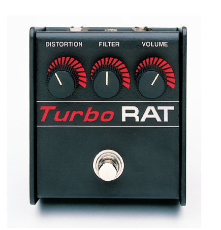
- Turbo-RAT is the distortion that was used by one of my favourite 90s bands: Teenage Fanclub
- βr (Beta or hFE reverse) is a technique used on the Fuzz War pedal by DeathByAudio, designed by Oliver Ackermann, singer and guitarrist of one of my favourite 2000s bands: A Place to Bury Strangers
- Octave Up was kind of a wink to noisy fuzz pedals like the Shin-Ei Fuzz used by Jesus & Mary Chain, one of my favourite bands of 80s, 90s that adds a doubler to increase high frecuency harmonics.
 |
| Gerard Love, TFC bassist, showing a Turbo RAT pedal (picture from Bandwagonesque album vinyl jacket) |
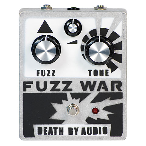 |
| Fuzz War pedal by Death by Audio |
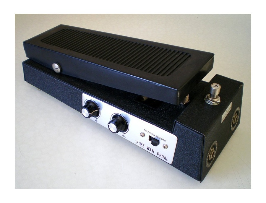 |
| Shin-Ei Fuzz Wah pedal |
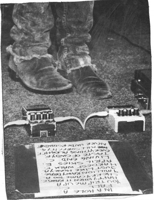 |
William Reid "pedalboard" (Fuzz-Wah on the right)
|
So the Rezz-Fuzz 3 in 1 pedal basically had to be a:
RAT + βr + Octave Up
Apart from that, I wanted to experiment with different type of diodes for the hard clipping section of the RAT distortion part.
The main issue was that mixing both pedals into one would require too many knobs: 3 for the RAT, 3 for the Fuzz War, plus one for the octave up, plus at least 2 switch buttons: one for clipping diode selection and at least one for effect switching, that is far too many controls for a single pedal to be packed in a 1590BB box.
Some simplification had to be made, the first one was to remove tone control on the RAT and replace it by octave up control. But since only one effect is used at a time, it would be good to reuse the same knobs for both effects. The solution was to use analog SPDT switches for two potentiometers on each of the 3 potentiometer contacts, plus another 2 SPDT switches for effect input and output selection. A 4053 device includes 3 SPDT switches, 3 of them were required.
Schematics
These are the schematics of the Rezz-Fuzz 3 in 1 effect in Eagle CAD:

On the top it's the βr or reverse hfe part of the circuit consisting of 7 transistor stages. At first sight there seems to be a big mistake on this circuit: Those NPN transistors seem to be inverted, but they are actually not, collector and emitter are inverted on purpose, actually base-emitter and base-collector both consist of a PN junction and they could be inverted, except that the gain of the resultant inverted transistor is what is called the βr (or hfe reverse) which usually is much lower than the direct gain. Here is an article from AMZ website that explains the characteristics of reverse beta amplifiers, apparently the clipping on a reversed transistor is quite different from a regular transistor generating different harmonics. The reason for having 7 transistors is because the gain on reverse beta transistors is much lower.
The problem with this is that actually the reverse hfe on most transistors is not specified, is not part of the manufacturing control process, and hence it may have wide variations. So the only choice here is manual selection after gain measurement with a multimeter able to measure hfe. On the other hand, this add a uniqueness to each pedal, and maybe the need to manually adjust resistors for each manufactured effect. The other issue is that I am not sure that Spice models can actually simulate the real behavior of transistor in reverse configuration. For this reason I will not include LTSpice simulations of the circuit.
I had to manually adjust the resistor values to make this circuit work, the final resistor values were very different from schematics published on internet. The recommended transistor base pull-ups were 430K on the first 5 stages and 910K on the last two stages, I had to change the value to 820K on the first 5 stages to properly bias the circuit and make it work. The recommended transistor emitter pull-downs were 390 ohms, I changed the values to 270 ohms. The recommended transistor collector pull-ups were 100K on the first 6 stages and 180K on the last 2 stages, I had to change the values to 1.2K in all stages in order to make it work.
In the middle of the schematics page, there are three 4053D 3-SPDT analog switch devices, the one on the left only uses two SPDT switches to select the input and the output of the selected effect (RAT or βr), the other two switch devices connect the three potentiomenter terminals to the desired effect. The switch device at the center is used to select the gain (RAT or βr) and the switch device on the right side of the page is used to select distortion/octave up mix for the RAT or tone for the βr effect.
At the bottom of the page it's the RAT effect with input and output buffer, soft clipping amplifier (that uses unbalanced diode clipping, R42 resistor is not installed) on top and octave-up on the bottom. Octave-up amplifier uses the feedback voltages between the feedback diodes and resistors to build a fully rectified version of the distorted signal.
The mix of soft-clipped signal and octave-up goes through a hard-clipping section where three options can be chosen: hard clipping with germanium diodes, no clipping or hard clipping with LED diodes.
On the bottom left side of the page it's the +9V DC input jack connector, battery terminals, an EMI filter, resistor divider to generate mid point voltage of +4.5V, decoupling capacitors and inversion protection diode.
On the top right side there is a 6-pin 0.1'' header footprint to solder a flat cable between the effect PCB and the 3PDT push-button foot switch PCB. A small PCB was designed in order to directly connect the foot switch and the PCB with a 0.1'' pitch flat cable.
PCB layout
The PCB was made on two layers with dimensions of 85 mm x 75 mm with chamfered corners to leave place for box screw holes. Three footswitch PCBs were also added.
 |
| PCB top layer |
 |
| PCB bottom layer |
The finished pedal with a Turbo RAT look:
 |
| Rezz Fuzz 3 in 1: RAT + βr + Octaver |
Source files
If you want to build your own RezzFuzz 3-in-1 pedal find Eagle 6.3.0 files (schematics, PCB, gerbers, BoM) on this github repository.