PCB Assembly
Circuit has been assembled on a 54 x 54 mm 2-layer PCB that fits into a 1590B enclosure.
Most components except 1N34A germanium diodes are SMD, with mainly 0402 passives. Phone jack connectors, DC jack connector, 9mm potentiometers and 5mm T1-3/4 LED are through-hole PCB mounted in order to minimize cabling. A 6-wire flat cable connects main to PCB 3-SPDT footswitch mounted on another small PCB. 9V battery clip is connected by 2 wires on +/- pads near the DC jack
 |
| Clean PCB before assembly |
Main ICs (opamps, DC-DC converter, voltage reference) are assembled first using solder paste and a hot air soldering station
 |
| Main ICs already assembled |
Passive and discrete components (ferrites, EMI filter, diodes, inductors, capacitors, resistors), mostly 0402, are then assembled using solder paste and hot air station.
 |
| PCB view with all SMD components assembled |
Through-hole components on bottom side (actually this side faces up): 9mm potentiometers and 5mm LED are then soldered using an iron and soldering wire:
 |
Klon 3v3 clone PCB bottom layer assembled
Through-hole components on top side: germanium diodes, phone jack connectors, DC jack connector are soldered using soldering wire and iron
 |
| Klon 3v3 clone PCB top layer assembled |
Once the circuit was fully assembled it seemed to fit well on the 1590B enclosure, but actually screwposts didn't allow the PCB border to touch the top enclosure sidewall so that DC jack would be receded probably avoiding proper DC plugging.
 |
Components fitting on 1590B enclosure
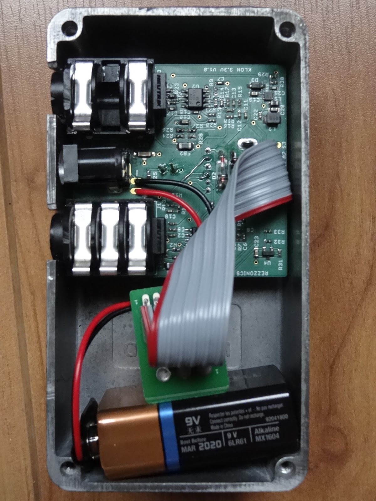
The PCB was finally mounted with connectors on one enclosure side. Next time PCB corners will have to be chamfered and connectors placed closer to the center in order to mount it with connectors on top side of the enclosure.
 |
| Klone 3v3 clone fully assembled |
Enclosure design and build
For the enclosure design I decided to use the etching technique. It was my second attempt and the results were not quite satisfactory.
Enclosure design was made using InkScape. A Star Wars trooper color image was converted to black and white, then inverted and mirrored, printed on a PNP blue paper with a laser printer and ironed on a previously sanded and polished enclosure.
 |
| Enclosure design made using Inkscape |
|
PNP transfer was a complete disaster so I finally used satin paper. Defaults were corrected with a permanent marker and etched
 |
| Enclosure view after PNP blue transfer (FAIL!!) |
Etching was made using a mix of hydrogen peroxide and hydrochloric acid which I think it is actually too strong, I finally over-etched the design corroding more areas than I should. Permanent marker did not protected well the aluminium from acid attack. The final result was quite modest.
 |
| Klon 3v3 clone pedal finished |
Plug it in and test!
|
 |
| Klon3v3 clone switched-on and ready for test |
Electrical Test
For electrical test, a Velleman PCSGU250 oscilloscope and signal generator was used. Three different signals were used: a 300mVpp 440Hz sinewave, a 300mVpp 4kHz sinewave, and a 300mVpp 1kHz guitar string note sampled. Signal is injected in the guitar pedal input and signals are probed with oscilloscope in different parts of the circuit with different gain and treble settings (0-5-10):
- first buffer opamp output (out1a),
- second gain opamp output (out1b),
- clipping diodes output (clip),
- third opamp output (out2a) and
- fourth tone opamp output (out2b)
At 440Hz with gain set at maximum, the total gain of the circuit is >23, 17 and 10dB with treble set at 10, 5 and 0 respectively. Saturation happens with gain and treble set to 10 with an output signal that has 3.25Vpp.
At 4kHz with gain set at 10, the total gain of the circuit is 14, 1.8 and -7.7dB with treble set at 10, 5 and 0 respectively. At 4.4kHz and an input of 300mV, the maximum output level is 1.5Vpp.
With a 300mVpp 1kHz guitar string note signal the maximum level obtained is 2.6Vpp (15dB gain)
|
|
| 440Hz sinewave 300mVpp input |
 |
| 440Hw sinewave 1620mVpp gain amplifier output (gain=10, 15dB) (out1b) |
 |
| 440Hw sinewave 181mVpp gain amplifier output (gain=5, -4.2dB) (out1b) |
 |
| 440Hw sinewave 22mVpp gain amplifier output (gain=0, -23dB) (out1b) |
 |
| 440Hz sinewave 340mVpp clipped signal (gain=10, 1.2dB) (clip) |
 |
| 440Hz sinewave 260mVpp clipped signal (gain=0-5, -1.1dB) (clip) |
 |
| 440Hz sinewave 1490mVpp second opamp output (gain = 10, 14dB) (out2a) |
 |
| 440Hz sinewave 820mVpp second opamp output (gain = 5, 9dB) (out2a) |
 |
| 440Hz sinewave 540mVpp second opamp output (gain = 0, 5.2dB) (out2a) |
 |
| 440Hz sinewave 3250Vpp tone opamp (treble=10, gain=10, 22.6dB) (out2b) |
 |
| 440Hz sinewave 2130mVpp tone amp output (treble=5, gain=10, 17dB) (out2b) |
 |
| 440Hz sinewave 970mVpp tone amp output (treble=0, gain=10, 10dB) (out2b) |
 |
| 4.4kHz sinewave 2010mVpp gain amplifier output (gain=10, 16.6dB) (out1b) |
 |
| 4.4kHz sinewave 290mVpp gain amplifier output (gain=5, -0.23dB) (out1b) |
 |
| 4.4kHz sinewave 190mVpp gain amplifier output (gain=0, -3.73dB) (out1b) |
 |
| 4.4kHz sinewave 760mVpp clipped signal (gain=10, 8.4dB) (clip) |
 |
| 4.4kHz sinewave 280mVpp clipped signal (gain=5, -0.43dB) (clip) |
 |
| 4.4kHz sinewave 220mVpp clipped signal (gain=0, -2.53dB) (clip) |
 |
| 4.4kHz sinewave 280mVpp second opamp output (gain=10, -0.63dB) (out2a) |
 |
| 4.4kHz sinewave 112mVpp second opamp output (gain=5, -8.53dB) (out2a) |
 |
| 4.4kHz sinewave 60mVpp second opamp output (gain=0, -14dB) (out2a) |
 |
| 4.4kHz sinewave 1500mVpp tone amp output (treble=10, gain=10, 14dB) (out2b) |
 |
| 4.4kHz sinewave 370mVpp tone amp output (treble=5, gain=10, 1.8dB) (out2b) |
 |
| 4.4kHz sinewave 120mVpp tone amp output (treble=0, gain=10, -7.7dB) (out2b) |
 |
| 1kHz guitar note 280mVpp input |
 |
| 1kHz guitar note 39mVpp output (gain=0, treble=0, -18dB) (out2b) |
 |
| 1kHz guitar note 115mVpp output (gain=0, treble=5, -8.3dB) (out2b) |
 |
| 1kHz guitar note 480mVpp output (gain=0, treble=10, 2.4B) (out2b) |
 |
| 1kHz guitar note 76mVpp output (gain=5, treble=0, -11dB) (out2b) |
 |
| 1kHz guitar note 220mVpp output (gain=5, treble=5, -3.7dB) (out2b) |
 |
| 1kHz guitar note 970mVpp output (gain=5, treble=10, 8dB) (out2b) |
 |
| 1kHz guitar note 210mVpp output (gain=10, treble=0, -4.5dB) (out2b) |
 |
| 1kHz guitar note 710mVpp output (gain=10, treble=5, 4.6dB) (out2b) |
 |
| 1kHz guitar note 2590mVpp output (gain=10, treble=10, 15dB) (out2b) |


Bonjour Monsieur,
ReplyDeleteI am curious as to the results of testing the 3.3V version with a guitar and amplifier. Any comments as to how it sounded (especially versus an original)...?
you are clear my mind actually after reading your article i got clear my complete doubt. thanks for such easy understanding post. Sharing on what is pinch off voltage for a jfet for future aspect at here http:// electrotopic.com/what-is-the-pinch-off-voltage-for-a-jfet/
ReplyDelete