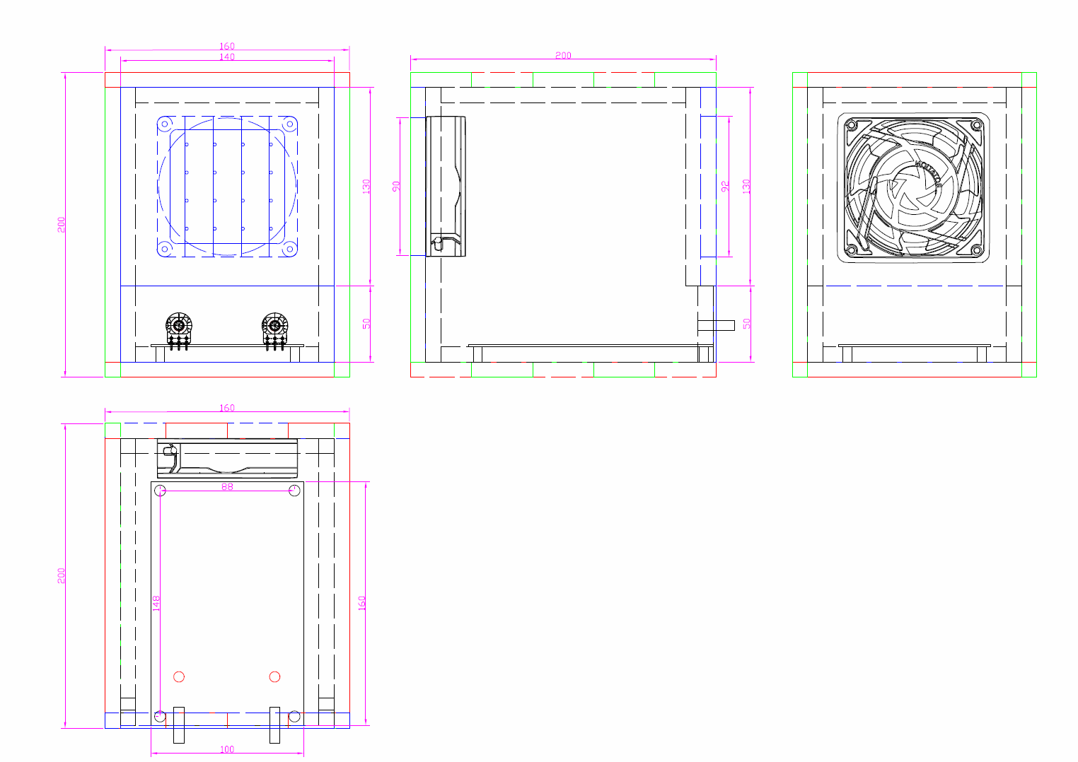
The enclosure was made using 10 mm thick plywood, with external dimensions of 160 x 200 x 200 mm (W x H x D)
Find here below mechanical drawings with dimensions. Front and rear sides are shown in blue. Top and bottom sides in red and left and right sides in green.
The box consists of a basic frame where left-right sides and top-bottom sides where joined using finger joints 40 mm long 10 mm deep. 3x40 mm fingers on each panel side are joined to 2x40 mm fingers on the adjacent panel. Wood paste was used to cover the
There is a squared chamfered 75 mm window in the front cover (140 x 130 mm), where the ionizer needle grid will be installed. An aluminum panel 140 x 50 mm and 2 mm thick is used to install 2 potentiometers, one switch and one blue LED.
The rear cover (180 x 140 mm) has a circular hole Ø90 mm for the fan air exhaust. All sides and corners are filed and rounded to allow covering with red tolex.
10 mm square wood cleats made out of the same plywood are used to reinforce the corners. they are glued leaving 10 mm distance to the front and rear borders to allow installing the front and rear covers. Only 2 mm are left for the aluminum plate on the front bottom side as shown in the picture below.
The box front panel as well as the inside has been painted in red. A red tolex has been glued on the top, bottom, left and right sides.
The PCB fully assembled with front panel, potentiometers, knobs, power-on switch and power-on blue LED. PCB has been connected with wire cables to the AC outlet, fan and ionizer needle grid ready for testing with a digital multimeter.
The rear panel has been covered with tolex too. The picture below shows the fan installed with a plastic fanguard with filter. A wire frame has been installed in order to place an additional disposable carbon filter.The AC outlet includes a fuse.
The needle grid is made out of 1 mm thick wire and nails. Four segments of wire where soldered to a square frame of wire. Four nails where soldered to each wire segment for a 16 pins needle grid.
The picture below shows the front panel with the needle grid installed as well as the aluminum faceplate with two knobs, power-on swith and power-on blue LED. The left button controls the output voltage of the ionizer, and the right button controls the speed of the fan. There is no risk in touching the needle grid or the screws connected to high voltage because they are protected with high impedance resistors, but an additional plastic cover could be added.
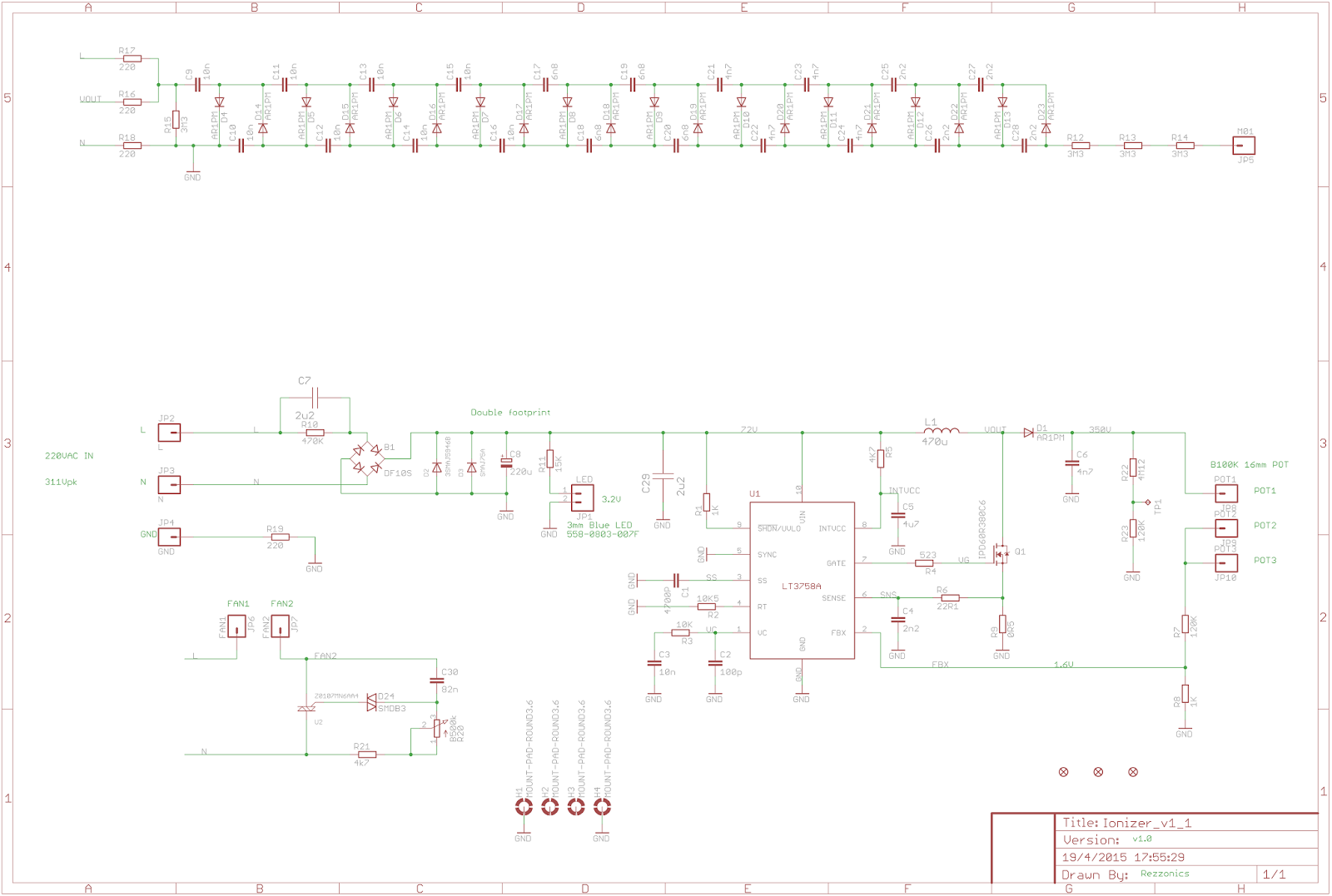
The figure below shows the schematics in Eagle CAD of the Negative Ion Generator.
At the bottom left, the AC fan speed controller based on a TRIAC, a DIAC, capacitor, resistor and 500kohm potentiometer. At the middle left, the 220VAC to 75VDC transformerless converter based on 75V Zener and TVS diodes. At the middle-center, the 75VDC to 350VDC step-up (boost) converter based on Linear Technology LT3758A and at the top the 20-stages capacitor-diode voltage multiplier connected to the switching node of the step-up converter. R15 3.3Mohm resistor allows discharging the voltage multipliers capacitors when the circuit is switched off.
C1 4.7nF generates a Soft-Start of the step-up converter that reduces current load at start-up. R2 10.5 kohm is chosen for a 1MHz frequency switching.
R5 must not be installed, otherwise U1 could be damaged!!
Please be aware that R17-R18 resistors are normally not installed, they allow bypassing the 220VAC to 75VDC and the 75VDC to 350VDC in order to connect the voltage multipliers directly to the mains. This is the traditional approach and much simpler negative ion generator that multiplies the 220VAC directly. This option was considered in case the step-up converter approach did not work properly. In this case, all the components between the 220VAC input L-N-GND (including R19) and POT1-2-3 are not installed, R16 is not installed and R17-R18 are installed instead. In this case the switching frequency goes from the 1MHz switching generated by LT3758A to the 50Hz frequency of the mains supply.
Typical diodes used in the voltage multiplier circuits are through-hole mounting devices 1N4007 (1kV). In this case 1kV avalanche SMD diodes AR1PM where used. Capacitor must be at least 1kV rated. Proper rating voltage has to be used in all components in order to withstand the high voltages of the circuit.
Below is the view of the PCB layout (160 x 100 mm). There is no reference ground plane underneath the high voltage area of the voltage multipliers to avoid arcing to GND. The 3.5kV and the 350V areas have been highlighted and labelled with silkscreen. TP1 test point is at 10V when the regulator output is at maximum voltage output of 350V, and at 5.5V when the output voltage is at minimum of 195V:
You can have access to the Bill of Materials on the Digikey website, please note that all components quantities are multiplied by two except for the fan and accessories.
As mentioned in the previous simulation blog entry, C7 2.2uF was not big enough to allow circuit start-up, due to initial peak current loads, so an additional 0.68uF capacitor (CGA9M4X7T2W684K200KA) had to be added in parallel to C7, to increase start-up current;
D2 75V Zener SMA diode had to be replaced by bigger SMB device (SMBJ5374B-TP) and 75V TVS SMA diode had to be replaced by bigger SMC device (SMCJ75A) to allow power dissipation at low loads.
ATTENTION!! Very high voltages are present on this circuit which can be harmful
Verification of the circuit has to be very careful and special safety measures has to be considered. I recommend wearing protective rubber gloves when probing the circuit to avoid getting an electric shock if inadvertently touching a high voltage point. The PCB input has 220VAC, the PCB area in the center, highlighted with silkscreen, from the output of LI and Q1 to R16 reaches 350VDC and the PCB area to the left with no ground reference plane from R15 to JP5, where all the capacitor-diodes voltage multipliers are located, goes from 350VDC to almost 3.5kV. Do not approach these high-voltages areas, the only points that need to be verified are the 75VDC output that can be probed at the right side of R11 or the right pin of JP1 if LED is not installed, and the test point TP1 that divides the output voltage of the DC-DC converter by 35. This test point will be between 5.5V to 10V depending on the position of the 100kohm potentiometer tap connected to POT1-2-3.
There is no risk if touching JP5 or the needle grid connected to it, since there are three 3.3Mohm resistors in series after the 3.5kV output of the voltage multipliers, if the needle grid is touched all the voltage will drop in this 10Mohm resistance.
The capacitor values used on the voltage multipliers are quite low so they do not store a lot of charge. I actually think that to increase the ionizer efficiency these capacitor values should be multiplied by 10, or all of them increased to 100nF, present values range from 10nF to 2.2nF. In this case a 1MHz frequency on the boost converter switching is probably not needed and it could be decreased.
The fan speed controller can actually been improved by increasing R21 from 4.7kohm to a higher value to be manually verified (probably between 100 kohm and 200 kohm), because the fan stops when R20 potentiometer tap is in the middle of its full sweep.
This project implies the generation of very high voltages that may be harmful.
Please check your own safety when working with high voltages, use protective measures like rubber gloves and avoid proximity to high voltage areas of the circuit.
______________________________
WARNING!!
This project could generate ozone levels that could be dangerous for your health.
ASHRAE recommends that ozone levels should not exceed 0.05 ppm.
CSA recommends an ozone limit of 0.04ppm.
I have no means to measure the possible generation of ozone on this device.
Use it at your own risk.
_______________________________
There is actually a lot of controversy going around regarding the dangers, safety and healthy properties of air purifiers, negative ion or ozone generators, specially regarding some cheap models found on the internet. I don't want to hide these discussions and I invite you to inform you on this matter before you decide to go on and build a negative ion generator. Use it at your own risk. I will post some videos at the end of this post.
Many years ago I discovered an article on an electronic magazine on a simple negative ion generator, based on cascaded capacitor-diode voltage multiplier from a regular 220VAC mains supply. The article described the benefits of negative ions as air purifier, removing dust, pollen and other contaminants from air, the presence of negative ions on water falls and other idylic places where you find calm and relaxation, how the air is charged with positive ions before a storm creating an oppressive and heavy atmosphere and how the air is charged with negative ions after the storm. So I decided to make this simple negative ion generator with a single big needle that concentrated a high negative voltage on its tip.
In order to test it I filled a glass jar with smoke and I put the needle inside the inverted jar so that the smoke could not slip out. When the generator was switched on a turbulence was created within the container and after a couple of minutes there was no trace of smoke inside the jar. I showed the smoke test to my father and he was so impressed that asked me to make an ion generator to put on his office, at the time it was allowed to smoke in the work places.
I found on another electronic magazine another negative ion generator boxed kit that had several needles. The circuit was a bit more complex, using an oscillator at higher frequency and a high voltage transformer plus the capacitor-diode voltage multipliers at the end. It worked OK but the dust and smoke deposited on the plastic box and around it leaving a dark stain around the ion generator, the transformer also generated a high pitch noise almost inaudible but that could be annoying at a work place.
The tips of the needles glowed and there was this peculiar ozone smell, which I found quite pleasant that reminded this smell after a storm. By reading through internet I found that a too high negative voltage (corona effect) can actually ionize the oxygen in the air and create ozone, which actually can be harmful if one is exposed to certain levels for a long time.
Years later I decided to make my own negative ion generator design but adding several features:
A quiet fan with variable speed to move dirty air through the ion generator
A disposable carbon filter where the dirt could be retained
A variable ionizing high voltage
Avoid the use of noisy and bulky transformers
I thought of using a high voltage (around 220Vrms) oscillator at a higher frequency than the mains 50/60Hz so that could be easily filtered with low capacitor values, for example 1MHz.
A step-up switching regulator actually chops a DC voltage generating a square wave that can then be filtered to a DC voltage with a capacitor-diode filter. If the regulator is adjustable by adding a potentiometer in the feedback input of the regulator, the converter generates a square signal that once filtered could generate and adjustable DC voltage output, then reusing the same square voltage output of the regulator and adding a capacitor-voltage multiplier a high negative voltage output could be also generated.
The first step was to find a step-up DC-DC regulator with the highest input voltage possible. Initially I thought that I should use an inverting regulator where the output voltage should be negative, since the voltage multiplier had to generate a negative high voltage, but actually I could connect a simple capacitor-diode to generate a positive regulated output voltage to be used by the feedback resistor bridge and in parallel connect the capacitor-diode voltage multiplier to generate the high negative voltage.
I found a Linear Technology step-up regulator, LT3758A that could fit my needs. This device supports an input voltage of up to 100V, there are not many DC-DC regulators that actually support this high input voltage. This device can be used in isolated flyback, SEPIC, inverting (my first idea) and boost (step-up) configuration. I used it in boost configuration.
The next step was to generate a DC high input voltage from the mains 220VAC supply, the usual method would be to use a transformer, but I wanted to get rid of the transformer. Usually a negative ion generator does not need very high currents since the goal is to generate a very high negative voltage that generates negative ions in the air, so the current required is mostly the current generated by the switching regulator plus the leaked current through the air and capacitor slow discharge.
An easy transformerless AC-DC power supply uses a resistor-capacitor impedance followed by a diode bridge and a zener diode to set up the output voltage. In order to be in the secure zone of the voltage regulator I decided to use 75VDC output at 120mA output current for a total of less than 10W power consumption.
Finally I selected a quiet 220VAC fan, the ORION OA92-22-2TB, and a speed regulator circuit based on a triac and a diac.
LTSpice simulations:
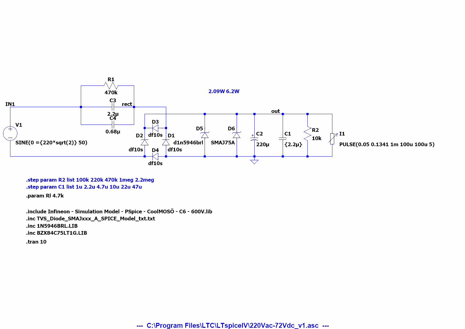
The figure below shows negative ion main circuit simulations schematics consisting of 75V to 350V step-up regulator and capacitor-diode voltage multiplier with 20 stages.
The figure below shows the waveforms of the switching signal at the output of the MOSFET and inductor (Vi1), and the "regulated" output voltage (Vo1) with the output voltage control potentiometer at minimum, 120 kohm on the top resistor and 1 kohm on the bottom resistor for a Vfb=1.6V, which corresponds to Vo1 = 194V. The output voltage is approximately 200V, it shows a lot of ripple because the capacitor used for the diode-capacitor filter is quite low, 4.7nF, but the goal is to keep the regulator switching to actually charge the voltage multiplier.
The figure below shows the output of the 20 capacitor-diode stages voltage multiplier (Vout) which is approximately -1.8kV, which corresponds to a voltage multiplication factor of more than 9 times.
The figure below shows the waveforms of the switching signal at the output of the MOSFET and inductor (Vi1), and the "regulated" output voltage (Vo1) with the output voltage control potentiometer at maximum, 220 kohm on the top resistor and 1 kohm on the bottom resistor for a Vfb = 1.6V, which corresponds to Vo1 = 353V. The output voltage is approximately 350V.
The figure below shows the output of the 20 capacitor-diode stages voltage multiplier (Vout) which is approximately -3.3kV !!
Below are the schematics of the 220VAC to 75VDC transformerless converter based on 2.2uF capacitor, bridge diode, 75V Zener diode and 75V TVS diode. The TVS diode has been added for extra overvoltage protection. The circuit is calculated for a current consumption of less than 150mA.
The figure below shows the output voltage of the transformerless AC-DC regulator, for an initial current of 120mA, followed by a zero current load, the output voltage goes from 75V @ 120mA to 84V @ 0mA:
This circuit actually has an issue because it has an almost constant power consumption of 75Vx120mA= 9W, if there is no load, most of the power consumption goes to the Zener and TVS diodes which actually could get hot and even exceed maximum power dissipation. The following figure shows the power consumption on the load, the 75V Zener diode and the 75V TVS diode at 120mA and at 0 mA:
When the load is at maximum 120mA most of the power, 8.7W, is dissipated by the load, but at a low load of 50mA only 4W are dissipated by the load and the rest of the power goes to the 75V Zener diode, 2W, and almost 4W to the 75V TVS diode, peak power of 10W but RMS power of 5W.
The problem of this circuit is that the load is quite variable, the 75V to 350V step-up DC-DC converter demands a peak of current at start-up but once the output capacitors are charged there is almost no current consumption apart from the switching to keep the capacitors charged. Zener diode has to be calculated for 3W or more and TVS diode for 5W or more to have some margin and they still will get hot.
Actually once the circuit was finished, the peak current at start-up was excessive and the output of the AC-DC never got to 75V, the 2.2uF capacitor (C3 in the simulation schematics) had to be increased adding a 0.68uF capacitor (C4). This value was manually adjusted by progressively increasing the capacity from 0.1uF until the AC-DC output reached 75V, but then, when the load was low, Zener and TVS diodes exceeded their rated power.
The 75V Zener diode had to be changed from an SMA 3W to an SMC 5W, and the 75V TVS diode had to be changed from SMA 3.3W to SMC 6.5W.
_________________
Controversy around the safety of negative ion generators, air purifiers, ozone generators: